Table Of Contents
Cisco IOS Switching Paths Overview
This chapter describes switching paths that can be configured on Cisco IOS devices. It contains the following sections:
Basic Router Platform Architecture and Processes
To understand how switching works, it helps to
first understand the basic router architecture and where various
processes occur in the router.
Fast switching is enabled by default on all
interfaces that support fast switching. If you have a situation where
you need to disable fast switching and fall back to the
process-switching path, understanding how various processes affect the
router and where they occur will help you determine your alternatives.
This understanding is especially helpful when you are troubleshooting
traffic problems or need to process packets that require special
handling. Some diagnostic or control resources are not compatible with
fast switching or come at the expense of processing and switching
efficiency. Understanding the effects of those resources can help you
minimize their effect on network performance.
Figure 2
illustrates a possible internal configuration of a Cisco 7500 series
router. In this configuration, the Cisco 7500 series router has an
integrated Route Switch Processor (RSP) and uses route caching
to forward packets. The Cisco 7500 series router also uses Versatile
Interface Processors (VIPs), a RISC-based interface processor that
receives and caches routing information from the RSP. The VIP card uses
the route cache to make switching decisions locally, which relieves the
RSP of involvement and speeds overall throughput. This type of switching
is called distributed switching. Multiple VIP cards can be installed in one router.
Figure 2 Basic Router Architecture

Cisco Routing and Switching Processes
The routing, or forwarding, function comprises two interrelated processes to move information in the network:
• Making a routing decision by routing
•Moving packets to the next hop destination by switching
Cisco IOS platforms perform both routing and switching, and there are several types of each.
Routing Processes
The routing process assesses the source and
destination of traffic based on knowledge of network conditions. Routing
functions identify the best path to use for moving the traffic to the
destination out one or more of the router interfaces. The routing
decision is based on various criteria such as link speed, topological
distance, and protocol. Each protocol maintains its own routing
information.
Routing is more processing intensive and has
higher latency than switching as it determines path and next hop
considerations. The first packet routed requires a lookup in the routing
table to determine the route. The route cache is populated after the
first packet is routed by the route-table lookup. Subsequent traffic for
the same destination is switched using the routing information stored
in the route cache.
Figure 3 illustrates the basic routing process.
Figure 3 The Routing Process

A router sends routing updates out each of its
interfaces that are configured for a particular protocol. It also
receives routing updates from other attached routers. From these
received updates and its knowledge of attached networks, it builds a map
of the network topology.
Switching Processes
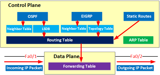
Through the switching process, the router
determines the next hop toward the destination address. Switching moves
traffic from an input interface to one or more output interfaces.
Switching is optimized and has lower latency than routing because it can
move packets, frames, or cells from buffer to buffer with simpler
determination of the source and destination of the traffic. It saves
resources because it does not involve extra lookups. Figure 4 illustrates the basic switching process.
Figure 4 The Switching Process

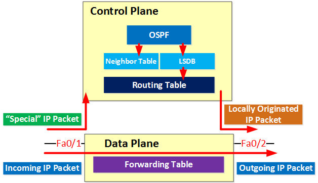
In Figure 4,
packets are received on the Fast Ethernet interface and destined for
the FDDI interface. Based on information in the packet header and
destination information stored in the routing table, the router
determines the destination interface. It looks in the routing table of
the protocol to discover the destination interface that services the
destination address of the packet.
The destination address is stored in tables
such as ARP tables for IP or AARP tables for AppleTalk. If there is no
entry for the destination, the router will either drop the packet (and
inform the user if the protocol provides that feature) or discover the
destination address by some other address resolution process, such as
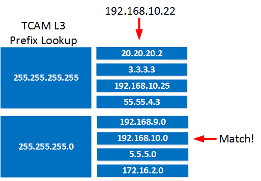
through ARP. Layer 3 IP addressing information is mapped to the Layer 2
MAC address for the next hop. Figure 5 illustrates the mapping that occurs to determine the next hop.
Figure 5 Layer 3-to-Layer 2 Mapping

Basic Switching Paths
Basic switching paths are described in the following sections:
Process Switching
In process switching the first packet is copied
to the system buffer. The router looks up the Layer 3 network address
in the routing table and initializes the fast-switch cache. The frame is
rewritten with the destination address and sent to the outgoing
interface that services that destination. Subsequent packets for that
destination are sent by the same switching path. The route processor
computes the cyclical redundancy check (CRC).
Fast Switching
When packets are fast switched, the first
packet is copied to packet memory and the destination network or host is
found in the fast-switching cache. The frame is rewritten and sent to
the outgoing interface that services the destination. Subsequent packets
for the same destination use the same switching path. The interface
processor computes the CRC. Fast switching is described in the "Configuring Fast Switching" chapter later in this publication.
CEF Switching
When CEF mode is enabled, the CEF FIB and
adjacency tables reside on the RP, and the RP performs the express
forwarding. You can use CEF mode when line cards are not available for
CEF switching or when you need to use features not compatible with dCEF
switching. For information on configuring CEF, see the "Cisco Express Forwarding Overview" chapter later in this publication.

Note Beginning
with Cisco IOS Release 12.0, CEF is the preferred and default switching
path. NetFlow switching has been integrated into CEF switching. For
information on NetFlow switching, see the "Cisco Express Forwarding Overview" chapter and the "Configuring Cisco Express Forwarding" chapter later in this publication.
dCEF Switching
In distributed switching, the switching process
occurs on VIP and other interface cards that support switching. When
dCEF is enabled, line cards, such as VIP line cards or GSR line cards,
maintain an identical copy of the FIB and adjacency tables. The line
cards perform the express forwarding between port adapters, relieving
the RSP of involvement in the switching operation. dCEF uses an Inter
Process Communication (IPC) mechanism to ensure synchronization of FIBs
and adjacency tables on the RP and line cards.
For model numbers and hardware compatibility information, refer to the Cisco Product Catalog. For information on configuring dCEF, see the "Configuring Cisco Express Forwarding" chapter later in this publication.
For information on configuring Multicast Distributed Switching (MDS), see the "Configuring Multicast Distributed Switching" chapter later in this publication.
Figure 6 illustrates the distributed switching process on the Cisco 7500 series.
Figure 6 Distributed Switching on Cisco 7500 Series Routers

The VIP card installed in this router maintains
a copy of the routing cache information needed to forward packets.
Because the VIP card has the routing information it needs, it performs
the switching locally, making the packet forwarding much faster. Router
throughput is increased linearly based on the number of VIP cards
installed in the router.
Platform and Switching Path Correlation
Depending on the routing platform you are using, availability and default implementations of switching paths varies. Table 3 shows the correlation between Cisco IOS switching paths and routing platforms.
Features That Affect Performance
Performance is derived from the switching
mechanism you are using. Some Cisco IOS features require special
handling and cannot be switched until the additional processing they
require has been performed. This special handling is not processing that
the interface processors can do. Because these features require
additional processing, they affect switching performance. These
features include the following:
•Filtering (using access lists)
For information on Quality of Service (QoS) performance, refer to the Cisco IOS Quality of Service Solutions Configuration Guide.