Sunday 28 December 2014

Multicast RPF

Multicast Reverse Path Forwarding 


One of the key differences between unicast and multicast is that for unicast routing we only care about where the destination is located and how to get there. For multicast routing we care about where the source is located. PIM (Protocol Independent Multicast) uses the unicast routing table to check what interface will be used to reach the source.
PIM will only accept multicast packets on an interface that we use to reach the source. If we receive multicast packets on an interface that we don’t use to reach the source, we will drop the multicast packets! This is called a RPF failure

Introduction:

In normal routing i.e. in Unicast routing packet forwarding decisions are typically based on the destination address of the packet arriving at a router. The unicast routing table is organized by destination subnet and mainly set up to forward the packet toward the destination.
In IP multicast routing, the router forwards the packet away from the source to make progress along the distribution tree and prevent routing loops. The router's multicast forwarding state runs more logically by organizing tables based on the reverse path, from the receiver back to the root of the distribution tree. This process is known as reverse-path forwarding (RPF).
In short, Incoming multicast packet will not be accepted/forwarded unless it is received on an interface that is the outgoing interface for unicast route to the source of the packet.

Configuration Example:

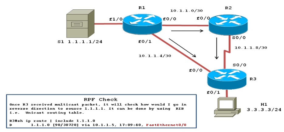
In below example multicast server S1 sends a multicast packet, with R1 flooding it to R2 and R3.R2 received its copy, and floods it as well. As a result R3 receives the same packet from two routers:
a) On its interface fa0/0 from R1.
b) On its interface s0/0 from R2.
Topology Diagram:
multicast_rpf1.jpg

Without the RPF check, R3 would forward the packet it got from R1 to R2, and vice versa, and begin the process of looping packets also with the same logic, R1 and R2 also keep repeating the process. This duplication creates multicast routing loops and generates multicast storms that waste bandwidth and router resources.
Before I dive into multicast configuration, let me share with you the initial configuration of our network. All relevant configurations are below.

R1R2R3
hostname R1

ip cef
!
ip multicast-routing
!
interface FastEthernet1/0
ip address 1.1.1.1 255.255.255.0
ip pim dense-mode
!
interface FastEthernet0/0
ip address 10.1.1.1 255.255.255.252
ip pim dense-mode
speed 100
full-duplex
!
interface FastEthernet0/1
ip address 10.1.1.5 255.255.255.252
ip pim dense-mode
speed 100
full-duplex
!
router eigrp 1
network 1.1.1.1 0.0.0.0
network 10.1.1.0 0.0.0.255
no auto-summary

hostname R2
!
ip multicast-routing
!
interface FastEthernet0/0
ip address 10.1.1.2 255.255.255.252
ip pim dense-mode
speed 100
full-duplex
!
interface Serial0/0
ip address 10.1.1.9 255.255.255.252
ip pim dense-mode
clock rate 2000000
!
router eigrp 1
network 10.1.1.0 0.0.0.255
no auto-summary
!


hostname R3
!
ip cef
!
ip multicast-routing
!
interface FastEthernet0/0
ip address 10.1.1.6 255.255.255.252
ip pim dense-mode
no ip route-cache
no ip mroute-cache
speed 100
full-duplex
!
interface FastEthernet0/1
ip address 3.3.3.3 255.255.255.0
ip pim dense-mode
ip igmp join-group 239.1.1.1
!
interface Serial0/0
ip address 10.1.1.10 255.255.255.252
ip pim dense-mode
no ip route-cache
no ip mroute-cache
clock rate 2000000
!
router eigrp 1
network 3.3.3.3 0.0.0.0
network 10.1.1.0 0.0.0.255
no auto-summary
!

When R3 performs the RPF check the following things will happen:
1) R3 examines the Source address of each incoming packet, which is 1.1.1.1.
2) R3 determines the reverse path interface based on its route used to forward packets to 1.1.1.1
In our case R3's route to 1.1.1.1/24 is matched, and it is lists an outgoing interface fa0/0, making fa0/0 R3's RPF interface for IP address 1.1.1.1
R3#sh ip route | beg Gate
Gateway of last resort is not set

     1.0.0.0/24 is subnetted, 1 subnets
D       1.1.1.0 [90/156160] via 10.1.1.5, 02:01:51, FastEthernet0/0
     3.0.0.0/24 is subnetted, 1 subnets
C       3.3.3.0 is directly connected, Loopback0
     10.0.0.0/30 is subnetted, 3 subnets
C       10.1.1.8 is directly connected, Serial0/0
D       10.1.1.0 [90/30720] via 10.1.1.5, 04:24:40, FastEthernet0/0
C       10.1.1.4 is directly connected, FastEthernet0/0

R3#sh ip rpf 1.1.1.1
RPF information for ? (1.1.1.1)
RPF interface: FastEthernet0/0
RPF neighbor: ? (10.1.1.5)
RPF route/mask: 1.1.1.0/24
RPF type: unicast (eigrp 1)
RPF recursion count: 0
Doing distance-preferred lookups across tables

R3#sh ip mroute | beg Interfac
Interface state: Interface, Next-Hop or VCD, State/Mode

(*, 239.1.1.1), 00:38:46/stopped, RP 0.0.0.0, flags: DCL
Incoming interface: Null, RPF nbr 0.0.0.0
Outgoing interface list:
   Loopback0, Forward/Dense, 00:38:46/00:00:00
   FastEthernet0/0, Forward/Dense, 00:38:46/00:00:00
   Serial0/0, Forward/Dense, 00:38:46/00:00:00
(1.1.1.1, 239.1.1.1), 00:00:26/00:02:37, flags: LT
Incoming interface: FastEthernet0/0, RPF nbr 10.1.1.5
Outgoing interface list:
   Loopback0, Forward/Dense, 00:00:26/00:00:00
   Serial0/0, Prune/Dense, 00:00:26/00:02:34, A

3) R3 compares the reverse path interface fa0/0 on which multicast packet arrives .If they match, it accepts the packets and forward it; otherwise ,it drops the packet .In this case ,R3 floods the packets received on fa0/0 from R1 but it ignore the packets received on s0/0 from R2.

Verification:

1) To verify we will be sending ICMP echo to group 239.1.1.1 from R1 with source 1.1.1.1.It's always safe to collect debugging logs in buffer rather than on console hence we will be debugging multicast packet and collect it in logging buffer as shown below:
R3#conf t
Enter configuration commands, one per line. End with CNTL/Z.
R3(config)#logging console informational
R3(config)#logging buffer 7
R3(config)#logging buffer 64000
R3(config)#no ip cef
R3(config)#end
*Mar 1 04:44:41.670: %SYS-5-CONFIG_I: Configured from console by console
R3#debug ip mpacket
IP multicast packets debugging is on

R1#ping 239.1.1.1 source 1.1.1.1

Type escape sequence to abort.
Sending 1, 100-byte ICMP Echos to 239.1.1.1, timeout is 2 seconds:
Packet sent with a source address of 1.1.1.1

Reply to request 0 from 10.1.1.6, 24 ms
Reply to request 0 from 10.1.1.6, 128 ms

R3#sh logging | beg Log
Log Buffer (64000 bytes):

IP(0): s=10.1.1.5 (FastEthernet0/0) d=239.1.1.1 (Serial0/0) id=19, ttl=254, prot=1, len=100(100), mforward
IP(0): s=10.1.1.1 (Serial0/0) d=239.1.1.1 id=19, ttl=253, prot=1, len=104(100), not RPF interface
IP(0): s=10.1.1.5 (FastEthernet0/0) d=239.1.1.1 (Serial0/0) id=20, ttl=254, prot=1, len=100(100), mforward
IP(0): s=10.1.1.1 (Serial0/0) d=239.1.1.1 id=20, ttl=253, prot=1, len=104(100), not RPF interface
IP(0): s=1.1.1.1 (FastEthernet0/0) d=239.1.1.1 (Serial0/0) id=20, ttl=253, prot=1, len=100(100), mforward
IP(0): s=1.1.1.1 (Serial0/0) d=239.1.1.1 id=20, ttl=252, prot=1, len=104(100), not RPF interface

From the above logs we can see that R3 forwarded the packets received on fa0/0 from R1 but it ignore the packets received on s0/0 from R2.
2) Let’s look it same with mtrace from R1 and capturing packet with the help wireshark on  R3’s interface Fa0/0 and S0/0.
R1#mtrace 1.1.1.1 3.3.3.3 239.1.1.1
Type escape sequence to abort.
Mtrace from 1.1.1.1 to 3.3.3.3 via group 239.1.1.1
From source (?) to destination (?)
Querying full reverse path...
0 3.3.3.3
-1 10.1.1.6 PIM  [1.1.1.0/24]
-2 10.1.1.5 PIM [1.1.1.0/24]
-3 1.1.1.1

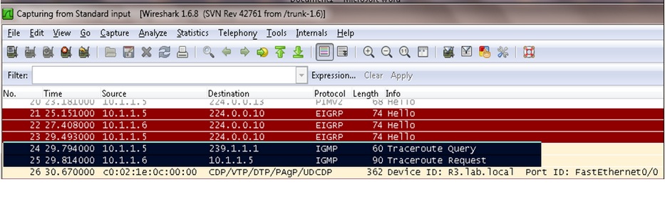
On R3’s interface fa0/0 we capture trace route query and request as mark in black box below diagram:
1.jpg
Let's open the traceroute request packet to get more detail inside view.
2.jpg
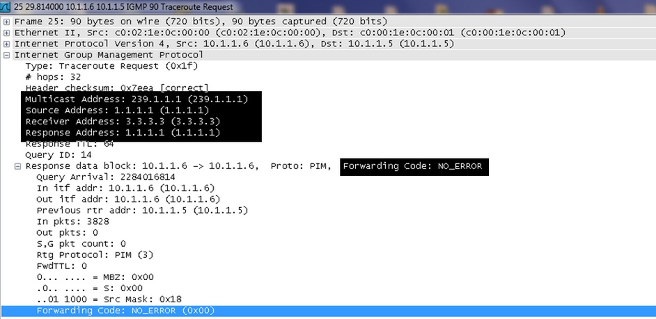
As show in above figure “FORWARDING CODE: NO_ERROR” field shows that after the router receives a multicast packet it performed an RPF check as the RPF check succeeds, the packet is forwarded.
Now let’s view capture taken on interface S0/0:
3.jpg

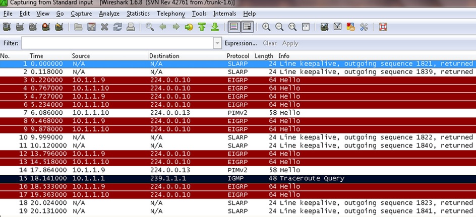
It is only showing trace route query not request as packets are drop due to RPF check failure.
Hence conclusion is the RPF check is a strategy by which router accept packets that arrives over the shortest path and discard those that arrive over longer routes and thereby avoid routing loops and duplication.

Thursday 25 December 2014

Anycast RP

Anycast RP


IP multicast is deployed as an integral component in mission-critical networked applications throughout the world. These applications must be robust, hardened, and scalable to deliver the reliability that users demand.
Using Anycast RP is an implementation strategy that provides load sharing and redundancy in Protocol Independent Multicast sparse mode (PIM-SM) networks. Anycast RP allows two or more rendezvous points (RPs) to share the load for source registration and the ability to act as hot backup routers for each other. Multicast Source Discovery Protocol (MSDP) is the key protocol that makes Anycast RP possible.
The scope of this document is to explain the basic concept of MSDP and the theory behind Anycast RP. It also provides an example of how to deploy Anycast RP.
This document has the following sections:

Multicast Source Discovery Protocol Overview

In the PIM sparse mode model, multicast sources and receivers must register with their local rendezvous point (RP). Actually, the router closest to a source or a receiver registers with the RP, but the key point to note is that the RP "knows" about all the sources and receivers for any particular group. RPs in other domains have no way of knowing about sources located in other domains. MSDP is an elegant way to solve this problem.
MSDP is a mechanism that allows RPs to share information about active sources. RPs know about the receivers in their local domain. When RPs in remote domains hear about the active sources, they can pass on that information to their local receivers. Multicast data can then be forwarded between the domains. A useful feature of MSDP is that it allows each domain to maintain an independent RP that does not rely on other domains, but it does enable RPs to forward traffic between domains. PIM-SM is used to forward the traffic between the multicast domains.
The RP in each domain establishes an MSDP peering session using a TCP connection with the RPs in other domains or with border routers leading to the other domains. When the RP learns about a new multicast source within its own domain (through the normal PIM register mechanism), the RP encapsulates the first data packet in a Source-Active (SA) message and sends the SA to all MSDP peers. Each receiving peer uses a modified Reverse Path Forwarding (RPF) check to forward the SA, until the SA reaches every MSDP router in the interconnected networks—theoretically the entire multicast internet. If the receiving MSDP peer is an RP, and the RP has a (*, G) entry for the group in the SA (there is an interested receiver), the RP creates (S, G) state for the source and joins to the shortest path tree for the source. The encapsulated data is decapsulated and forwarded down the shared tree of that RP. When the last hop router (the router closest to the receiver) receives the multicast packet, it may join the shortest path tree to the source. The MSDP speaker periodically sends SAs that include all sources within the domain of the RP. Figure 1 shows how data would flow between a source in domain A to a receiver in domain E.
MSDP was developed for peering between Internet service providers (ISPs). ISPs did not want to rely on an RP maintained by a competing ISP to provide service to their customers. MSDP allows each ISP to have its own local RP and still forward and receive multicast traffic to the Internet.
Figure 1 MSDP Example: MSDP Shares Source Information Between RPs in Each Domain

Anycast RP Overview

Anycast RP is a useful application of MSDP. Originally developed for interdomain multicast applications, MSDP used for Anycast RP is an intradomain feature that provides redundancy and load-sharing capabilities. Enterprise customers typically use Anycast RP for configuring a Protocol Independent Multicast sparse mode (PIM-SM) network to meet fault tolerance requirements within a single multicast domain.
In Anycast RP, two or more RPs are configured with the same IP address on loopback interfaces. The Anycast RP loopback address should be configured with a 32-bit mask, making it a host address. All the downstream routers should be configured to "know" that the Anycast RP loopback address is the IP address of their local RP. IP routing automatically will select the topologically closest RP for each source and receiver. Assuming that the sources are evenly spaced around the network, an equal number of sources will register with each RP. That is, the process of registering the sources will be shared equally by all the RPs in the network.
Because a source may register with one RP and receivers may join to a different RP, a method is needed for the RPs to exchange information about active sources. This information exchange is done with MSDP.
In Anycast RP, all the RPs are configured to be MSDP peers of each other. When a source registers with one RP, an SA message will be sent to the other RPs informing them that there is an active source for a particular multicast group. The result is that each RP will know about the active sources in the area of the other RPs. If any of the RPs were to fail, IP routing would converge and one of the RPs would become the active RP in more than one area. New sources would register with the backup RP. Receivers would join toward the new RP and connectivity would be maintained.
Note that the RP is normally needed only to start new sessions with sources and receivers. The RP facilitates the shared tree so that sources and receivers can directly establish a multicast data flow. If a multicast data flow is already directly established between a source and the receiver, then an RP failure will not affect that session. Anycast RP ensures that new sessions with sources and receivers can begin at any time.

Anycast RP Example

The main purpose of an Anycast RP implementation is that the downstream multicast routers will "see" just one address for an RP. The example given in Figure 2 shows how the loopback 0 interface of the RPs (RP1 and RP2) is configured with the same 10.0.0.1 IP address. If this 10.0.0.1 address is configured on all RPs as the address for the loopback 0 interface and then configured as the RP address, IP routing will converge on the closest RP. This address must be a host route—note the 255.255.255.255 subnet mask.
The downstream routers must be informed about the 10.0.0.1 RP address. In Figure 2, the routers are configured statically with the ip pim rp-address 10.0.0.1 global configuration command. This configuration could also be accomplished using the Auto-RP or bootstrap router (BSR) features.
The RPs in Figure 2 must also share source information using MSDP. In this example, the loopback 1 interface of the RPs (RP1 and RP2) is configured for MSDP peering. The MSDP peering address must be different than the Anycast RP address.
Figure 2 Anycast RP Configuration
Many routing protocols choose the highest IP address on loopback interfaces for the Router ID. A problem may arise if the router selects the Anycast RP address for the Router ID. We recommend that you avoid this problem by manually setting the Router ID on the RPs to the same address as the MSDP peering address (for example, the loopback 1 address in Figure 2). In Open Shortest Path First (OSPF), the Router ID is configured using the router-id router configuration command. In Border Gateway Protocol (BGP), the Router ID is configured using the bgp router-id router configuration command. In many BGP topologies, the MSDP peering address and the BGP peering address must be the same in order to pass the RPF check. The BGP peering address can be set using the neighbor update-source router configuration command.
The Anycast RP example in the previous paragraphs used IP addresses from RFC 1918. These IP addresses are normally blocked at interdomain borders and therefore are not accessible to other ISPs. You must use valid IP addresses if you want the RPs to be reachable from other domains.

Related Documents

IP Multicast Technology Overview, Cisco white paper
http://www.cisco.com/univercd/cc/td/doc/cisintwk/intsolns/mcst_sol/mcst_ovr.htm
Interdomain Multicast Solutions Using MSDP, Cisco integration solutions document
http://www.cisco.com/univercd/cc/td/doc/cisintwk/intsolns/mcst_p1/mcstmsdp/index.htm
Configuring a Rendezvous Point, Cisco white paper
http://www.cisco.com/univercd/cc/td/doc/cisintwk/intsolns/mcst_sol/rps.htm
"Configuring Multicast Source Discovery Protocol," Cisco IOS IP Configuration Guide, Release 12.2
http://www.cisco.com/univercd/cc/td/doc/product/software/ios122/122cgcr/fipr_c/ipcpt3/1cfmsdp.htm
"Multicast Source Discovery Protocol Commands," Cisco IOS IP Command Reference, Volume 3 of 3: Multicast, Release 12.2

http://www.cisco.com/univercd/cc/td/doc/product/software/ios122/122cgcr/fiprmc_r/1rfmsdp.htm

Saturday 20 December 2014

Multicast

Multicast

Multicast is a bandwidth-conserving technology that reduces traffic by simultaneously delivering a single stream of information to thousands of corporate recipients and homes. Applications that take advantage of multicast technologies include video conferencing, corporate communications, distance learning, and distribution of software, stock quotes, and news.

Multicast Group Concept


Multicast is based on the concept of a group. A multicast group is an arbitrary group of receivers that expresses an interest in receiving a particular data stream. This group has no physical or geographical boundaries—the hosts can be located anywhere on the Internet or any private internetwork. Hosts that are interested in receiving data flowing to a particular group must join the group using IGMP (IGMP is discussed in the "Internet Group Management Protocol (IGMP)" section later in this document). Hosts must be a member of the group to receive the data stream.

IP Multicast Addresses


IP multicast addresses specify a "set" of IP hosts that have joined a group and are interested in receiving multicast traffic designated for that particular group. IPv4 multicast address conventions are described in the following sections.

IP Class D Addresses


The Internet Assigned Numbers Authority (IANA) controls the assignment of IP multicast addresses. IANA has assigned the IPv4 Class D address space to be used for IP multicast. Therefore, all IP multicast group addresses fall in the range from 224.0.0.0 through 239.255.255.255.

Note The Class D address range is used only for the group address or destination address of IP multicast traffic. The source address for multicast datagrams is always the unicast source address.


Table 1 gives a summary of the multicast address ranges discussed in this document.

Table 1 Multicast Address Range Assignments

Description

Range

Reserved Link Local Addresses

224.0.0.0/24

Globally Scoped Addresses

224.0.1.0 to 238.255.255.255

Source Specific Multicast

232.0.0.0/8

GLOP Addresses

233.0.0.0/8

Limited Scope Addresses

239.0.0.0/8

Reserved Link Local Addresses


The IANA has reserved addresses in the range 224.0.0.0/24 to be used by network protocols on a local network segment. Packets with these addresses should never be forwarded by a router. Packets with link local destination addresses are typically sent with a time-to-live (TTL) value of 1 and are not forwarded by a router.

Network protocols use these addresses for automatic router discovery and to communicate important routing information. For example, Open Shortest Path First (OSPF) uses the IP addresses 224.0.0.5 and 224.0.0.6 to exchange link-state information. Table 2 lists some well-known link local IP addresses.

Table 2 Examples of Link Local Addresses

IP Address

Usage

224.0.0.1

All systems on this subnet

224.0.0.2

All routers on this subnet

224.0.0.5

OSPF routers

224.0.0.6

OSPF designated routers

224.0.0.12

Dynamic Host Configuration Protocol (DHCP) server/relay agent

Globally Scoped Addresses


Addresses in the range from 224.0.1.0 through 238.255.255.255 are called globally scoped addresses. These addresses are used to multicast data between organizations and across the Internet.

Some of these addresses have been reserved for use by multicast applications through IANA. For example, IP address 224.0.1.1 has been reserved for Network Time Protocol (NTP).

IP addresses reserved for IP multicast are defined in RFC 1112, Host Extensions for IP Multicasting. More information about reserved IP multicast addresses can be found at the following location:
http://www.iana.org/assignments/multicast-addresses.


Note You can find all RFCs and Internet Engineering Task Force (IETF) drafts on the IETF website (http://www.ietf.org).


Source Specific Multicast Addresses


Addresses in the 232.0.0.0/8 range are reserved for Source Specific Multicast (SSM). SSM is an extension of the PIM protocol that allows for an efficient data delivery mechanism in one-to-many communications. SSM is described in the "Source Specific Multicast (SSM)" section later in this document.

GLOP Addresses


RFC 2770, GLOP Addressing in 233/8, proposes that the 233.0.0.0/8 address range be reserved for statically defined addresses by organizations that already have an AS number reserved. This practice is called GLOP addressing. The AS number of the domain is embedded into the second and third octets of the 233.0.0.0/8 address range. For example, the AS 62010 is written in hexadecimal format as F23A. Separating the two octets F2 and 3A results in 242 and 58 in decimal format. These values result in a subnet of 233.242.58.0/24 that would be globally reserved for AS 62010 to use.

Limited Scope Addresses


Addresses in the 239.0.0.0/8 range are called limited scope addresses or administratively scoped addresses. These addresses are described in RFC 2365, Administratively Scoped IP Multicast, to be constrained to a local group or organization. Companies, universities, or other organizations can use limited scope addresses to have local multicast applications that will not be forwarded outside their domain. Routers typically are configured with filters to prevent multicast traffic in this address range from flowing outside of an autonomous system (AS) or any user-defined domain. Within an autonomous system or domain, the limited scope address range can be further subdivided so that local multicast boundaries can be defined. This subdivision is called address scoping and allows for address reuse between these smaller domains.

Layer 2 Multicast Addresses


Historically, network interface cards (NICs) on a LAN segment could receive only packets destined for their burned-in MAC address or the broadcast MAC address. In IP multicast, several hosts need to be able to receive a single data stream with a common destination MAC address. Some means had to be devised so that multiple hosts could receive the same packet and still be able to differentiate between several multicast groups.

One method to accomplish this is to map IP multicast Class D addresses directly to a MAC address. Today, using this method, NICs can receive packets destined to many different MAC addresses—their own unicast, broadcast, and a range of multicast addresses.

The IEEE LAN specifications made provisions for the transmission of broadcast and multicast packets. In the 802.3 standard, bit 0 of the first octet is used to indicate a broadcast or multicast frame. Figure 2 shows the location of the broadcast or multicast bit in an Ethernet frame. 

Figure 2 IEEE 802.3 MAC Address Format


This bit indicates that the frame is destined for a group of hosts or all hosts on the network (in the case of the broadcast address, 0xFFFF.FFFF.FFFF).

IP multicast makes use of this capability to send IP packets to a group of hosts on a LAN segment.


Tuesday 2 December 2014

DMVNP

Introduction:

This document gives a brief information about DMVPN with a configuration example where you can see DMVPN without IPSEC and with IPSEC.

What is DMVPN?

DMVPN stands for Dynamic Multipoint VPN and it is an effective solution for dynamic secure overlay networks. In short, DMVPN is combination of the following technologies:

  • Multipoint GRE (mGRE)
  • Next-Hop Resolution Protocol (NHRP)
  • Dynamic IPsec encryption
 
Dynamic Multipoint VPN (DMVPN) is Cisco’s answer to the increasing demands of enterprise companies to be able to connect branch offices with head offices and between each other while keeping costs low, minimizing configuration complexity and increasing flexibility.

With DMVPN, one central router, usually placed at the head office, undertakes the role of the Hub while all other branch routers are Spokes that connect to the Hub router so the branch offices can access the company’s resources. DMVPN consists of two mainly deployment designs:
  • DMVPN Hub & Spoke, used to perform headquarters-to-branch interconnections
  • DMVPN Spoke-to-Spoke, used to perform branch-to-branch interconnections
In both cases, the Hub router is assigned a static public IP Address while the branch routers (spokes) can be assigned static or dynamic public IP addresses.

Example:

Physical Connectivity:

DMVPN Operation - How DMVPN Operates

Before diving into the configuration of our routers, we’ll briefly explain how the DMVPN is expected to work. This will help in understanding how DMVPN operates in a network:
  • Each spoke has a permanent IPSec tunnel to the hub but not to the other spokes within the network.
  • Each spoke registers as a client of the NHRP server. The Hub router undertakes the role of the NHRP server.
  • When a spoke needs to send a packet to a destination (private) subnet on another spoke, it queries the NHRP server for the real (outside) address of the destination (target) spoke.
  • After the originating spoke learns the peer address of the target spoke, it can initiate a dynamic IPSec tunnel to the target spoke.
  • The spoke-to-spoke tunnel is built over the multipoint GRE (mGRE) interface.
  • The spoke-to-spoke links are established on demand whenever there is traffic between the spokes. Thereafter, packets are able to bypass the hub and use the spoke-to-spoke tunnel.
  • All data traversing the GRE tunnel is encrypted using IPSecurity (optional)


 configuration:

ROUTER 4 ISP

interface FastEthernet0/0
 ip address 192.168.1.1 255.255.255.0
 speed auto
 full-duplex
!
interface FastEthernet0/1
 ip address 192.168.2.1 255.255.255.0
 speed auto
 full-duplex
!
interface FastEthernet1/0
 ip address 192.168.3.1 255.255.255.0
 speed auto
 full-duplex


ROUTER 1 (Hub)

interface Loopback0
 ip address 192.168.0.1 255.255.255.0
 !
!
interface Tunnel0
 ip address 10.1.1.1 255.255.255.0
 no ip redirects
 ip nhrp map multicast dynamic
 ip nhrp network-id 1
 tunnel source 192.168.1.100
 tunnel mode gre multipoint
 !
!
interface FastEthernet0/0
 ip address 192.168.1.100 255.255.255.0
 duplex full
 speed auto
 !
!
ip route 192.168.2.0 255.255.255.0 192.168.1.1
ip route 192.168.3.0 255.255.255.0 192.168.1.1
!

ROUTER 2


!
interface Loopback0
 ip address 172.16.2.1 255.255.255.0
 !
!
interface Tunnel0
 ip address 10.1.1.2 255.255.255.0
 no ip redirects
 ip nhrp map 10.1.1.1 192.168.1.100
 ip nhrp map multicast 192.168.1.100
 ip nhrp network-id 1
 ip nhrp nhs 10.1.1.1
 tunnel source 192.168.2.2
 tunnel mode gre multipoint
 !
!
interface FastEthernet0/0
 ip address 192.168.2.2 255.255.255.0
 duplex full
 speed auto
 !

!
ip route 192.168.1.100 255.255.255.255 192.168.2.1
!

!


-==ROUTER 3
!
interface Loopback0
 ip address 172.16.3.1 255.255.255.0
 !
!
interface Tunnel0
 ip address 10.1.1.3 255.255.255.0
 no ip redirects
 ip nhrp map multicast 192.168.1.100
 ip nhrp map 10.1.1.1 192.168.1.100
 ip nhrp network-id 1
 ip nhrp nhs 10.1.1.1
 tunnel source 192.168.3.3
 tunnel mode gre multipoint
 !
!
interface FastEthernet0/0
 ip address 192.168.3.3 255.255.255.0
 duplex full
 speed auto
 !
!
interface FastEthernet0/1
 no ip address
 shutdown
 duplex auto
 speed auto
 !
!
!
ip forward-protocol nd
no ip http server
no ip http secure-server
!
!
ip route 192.168.1.100 255.255.255.255 192.168.3.1
!
!

-==== Until here we have the DMVPN without IPSEC-===

IPSEC:

Next you will need to add IPSEC, this will ensure that traffic is not sent in clear text. This configuration will be added to each router except router 4.

crypto isakmp policy 1
encr 3des
hash md5
authentication pre-share
group 2
crypto isakmp key firewall address 0.0.0.0 0.0.0.0
!
!
crypto ipsec transform-set TS esp-3des esp-md5-hmac
!
crypto ipsec profile protect-gre
set security-association lifetime seconds 86400
set transform-set TS
!
then 

(config-t) #
(config-if)#tunnel protection ipsec profile protect-gre

-=========
!!!!!!!!!!!!!!!!!!!!!!!!!!!!!!!!!!!!!!!!!!!!!!!!!!!!!!!!!!!!!!!!!!!!!!!!!!!!!!!!!!!!!!!
Verification

R1#sh dmvpn
Legend: Attrb --> S - Static, D - Dynamic, I - Incomplete
        N - NATed, L - Local, X - No Socket
        # Ent --> Number of NHRP entries with same NBMA peer
        NHS Status: E --> Expecting Replies, R --> Responding
        UpDn Time --> Up or Down Time for a Tunnel
==========================================================================

Interface: Tunnel0, IPv4 NHRP Details
Type:Hub, NHRP Peers:2,

 # Ent  Peer NBMA Addr Peer Tunnel Add State  UpDn Tm Attrb
 ----- --------------- --------------- ----- -------- -----
     1     192.168.2.2        10.1.1.2    UP 00:00:00     D
     1     192.168.3.3        10.1.1.3    UP 00:00:01     D


R1#sh crypto session
Crypto session current status

Interface: Tunnel0
Session status: UP-ACTIVE
Peer: 192.168.2.2 port 500
  IKE SA: local 192.168.1.100/500 remote 192.168.2.2/500 Active
  IKE SA: local 192.168.1.100/500 remote 192.168.2.2/500 Inactive
  IPSEC FLOW: permit 47 host 192.168.1.100 host 192.168.2.2
        Active SAs: 2, origin: crypto map

Interface: Tunnel0
Session status: UP-ACTIVE
Peer: 192.168.3.3 port 500
  IKE SA: local 192.168.1.100/500 remote 192.168.3.3/500 Active
  IKE SA: local 192.168.1.100/500 remote 192.168.3.3/500 Inactive
  IPSEC FLOW: permit 47 host 192.168.1.100 host 192.168.3.3
        Active SAs: 2, origin: crypto map

!!!!!!!!!!!!!!!!!!!!!!!!!!!!! R2

R2#sh dmvpn
Legend: Attrb --> S - Static, D - Dynamic, I - Incomplete
        N - NATed, L - Local, X - No Socket
        # Ent --> Number of NHRP entries with same NBMA peer
        NHS Status: E --> Expecting Replies, R --> Responding
        UpDn Time --> Up or Down Time for a Tunnel
==========================================================================

Interface: Tunnel0, IPv4 NHRP Details
Type:Spoke, NHRP Peers:1,

 # Ent  Peer NBMA Addr Peer Tunnel Add State  UpDn Tm Attrb
 ----- --------------- --------------- ----- -------- -----
     1   192.168.1.100        10.1.1.1    UP 00:08:19     SR2 


R2#sh crypto session
Crypto session current status

Interface: Tunnel0
Session status: UP-ACTIVE
Peer: 192.168.1.100 port 500
  IKE SA: local 192.168.2.2/500 remote 192.168.1.100/500 Active
  IPSEC FLOW: permit 47 host 192.168.2.2 host 192.168.1.100
        Active SAs: 2, origin: crypto map

!!!!!!!!!!!!!!R3

R3#sh dmvpn
Legend: Attrb --> S - Static, D - Dynamic, I - Incomplete
        N - NATed, L - Local, X - No Socket
        # Ent --> Number of NHRP entries with same NBMA peer
        NHS Status: E --> Expecting Replies, R --> Responding
        UpDn Time --> Up or Down Time for a Tunnel
==========================================================================

Interface: Tunnel0, IPv4 NHRP Details
Type:Spoke, NHRP Peers:1,

 # Ent  Peer NBMA Addr Peer Tunnel Add State  UpDn Tm Attrb
 ----- --------------- --------------- ----- -------- -----
     1   192.168.1.100        10.1.1.1    UP 00:08:59     S


R3#sh crypto session
Crypto session current status

Interface: Tunnel0
Session status: UP-ACTIVE
Peer: 192.168.1.100 port 500
  IKE SA: local 192.168.3.3/500 remote 192.168.1.100/500 Active
  IPSEC FLOW: permit 47 host 192.168.3.3 host 192.168.1.100
        Active SAs: 2, origin: crypto map