Network Diagram virtual link
This document uses this network setup: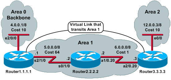
Configurations
This document uses these configurations:| Router1.1.1.1 |
|---|
Current configuration:

hostname Router1.1.1.1

interface Loopback0
 ip address 1.1.1.1 255.0.0.0

interface Ethernet2/0/0
 ip address 4.0.0.1 255.0.0.0

interface Serial2/1/0
 ip address 5.0.0.1 255.0.0.0

router ospf 2
 network 4.0.0.0 0.255.255.255 area 0
 network 5.0.0.0 0.255.255.255 area 1
 area 1 virtual-link 3.3.3.3

!--- Area 1 is the transit area. !--- IP address 3.3.3.3 is the router !--- ID of the router between Area 1 !--- and Area 2 (Router3.3.3.3). See !--- the next Note.

end
|
| Router2.2.2.2 |
|---|
Current configuration: hostname Router2.2.2.2 interface Loopback0 ip address 2.2.2.2 255.0.0.0 interface Serial0/1/0 ip address 5.0.0.2 255.0.0.0 interface ATM1/0.20 point-to-point ip address 6.0.0.2 255.0.0.0 router ospf 2 network 6.0.0.0 0.255.255.255 area 1 network 5.0.0.0 0.255.255.255 area 1 end |
| Router3.3.3.3 |
|---|
Current configuration:

hostname Router3.3.3.3

interface Loopback0
 ip address 3.3.3.3 255.0.0.0

interface Ethernet0/0
 ip address 12.0.0.3 255.0.0.0

interface ATM2/0.20 point-to-point
 ip address 6.0.0.3 255.0.0.0

router ospf 2
 network 12.0.0.0 0.255.255.255 area 2
 network 6.0.0.0 0.255.255.255 area 1
 area 1 virtual-link 1.1.1.1

!--- Area 1 is the transit area. !--- IP address 1.1.1.1 is the router !--- ID of the router between Area 1 !--- and Area 0 (Router1.1.1.1).

end
|
How the Virtual Link Operates
Initially, the virtual link is down because Router1.1.1.1 does not know how to reach Router3.3.3.3 (the other end of the virtual link). All of the link-state advertisements (LSAs) in Area 1 need to be flooded, and the shortest path first (SPF) algorithm must be run within Area 1 by all three routers, for Router1.1.1.1 to know how to reach Router3.3.3.3 through Area 1.After the routers know how to reach each other through the transit area, they try to form adjacency across the virtual link. The OSPF packets between the two ends of the virtual link are not multicast packets. They are tunneled packets from source 5.0.0.1 to the destination 6.0.0.3, because they are tunneled to the other end of the virtual link. It is important to note that if there is a firewall in between the virtual-link routers, you need to enable the OSPF (IP protocol 89) port between the virtual-link tunnel outgoing interface IPs that are between 5.0.0.1 and 6.0.0.3.
Once the routers become adjacent on the virtual link, Router3.3.3.3 considers itself an area border router (ABR), because it now has a link in Area 0. As a result, Router3.3.3.3 creates a summary LSA for 12.0.0.0/8 in Area 0 and in Area 1.
If the virtual link is misconfigured for some reason, then Router3.3.3.3 does not consider itself an ABR because it does not have any interfaces in Area 0. If this is the case, it does not create summary LSAs or advertise 12.0.0.0/8 into Area 1.
Note: OSPF runs on top of IP and uses protocol number 89. OSPF does not rely on any other transport protocols, such as TCP and UDP.
Calculate the Shortest Path
This section calculates the shortest path from the perspective of Router2.2.2.2.Router2.2.2.2 looks in its own LSA and sees that Router3.3.3.3 is a neighbor. It then looks at the LSA of Router3.3.3.3 to verify that Router3.3.3.3 sees Router2.2.2.2 as a neighbor. If both routers see each other as neighbors, then they are considered reachable.
Each router also checks its local neighbor table (which you can see with the show ip ospf neighbor command) to verify that its interface and the interface of the neighbor are on a common IP subnet.
Note: This check is not performed on an unnumbered interface.
If they are on a common subnet, the routers install routes for any stub networks listed in the router LSA of their neighbor. In this example, 6.0.0.0/8 is the only stub network listed in the LSA of Router3.3.3.3 in Area 1, to which Router2.2.2.2 is already directly connected.
Router3.3.3.3 does the same examination for the LSA of Router1.1.1.1, but there are not any useful stub networks in the LSA of Router1.1.1.1.
After all of the reachable router LSAs in Area 1 are examined, Router2.2.2.2 looks at summary LSAs in the database. It finds two summary LSAs for 12.0.0.0/8 in Area 1 and chooses the one with the lowest total cost, which is the metric to reach the advertising router plus the metric of the summary LSA.
- Router2.2.2.2 can reach 12.0.0.0 through Router1.1.1.1 with a cost of 64 + 75 = 139.
- Router2.2.2.2 can reach 12.0.0.0 through Router3.3.3.3 with a cost of 1 + 10 = 11.
This output shows the OSPF routes in the routing table of each router previously described:
Router1.1.1.1#show ip route ospf

!--- Output suppressed.

O    6.0.0.0/8 [110/65] via 5.0.0.2, 00:38:12, Serial2/1/0
O IA 12.0.0.0/8 [110/75] via 5.0.0.2, 00:38:02, Serial2/1/0

Router2.2.2.2#show ip route ospf

!--- Output suppressed.

O IA 4.0.0.0/8 [110/74] via 5.0.0.1, 00:38:08, Serial0/1/0
O IA 12.0.0.0/8 [110/11] via 6.0.0.3, 00:38:12, ATM1/0.20

!--- This is the route in this example.

Router3.3.3.3#show ip route ospf

!--- Output suppressed.

O    4.0.0.0/8 [110/75] via 6.0.0.2, 00:38:18, ATM2/0.20
O    5.0.0.0/8 [110/65] via 6.0.0.2, 00:38:28, ATM2/0.20
Using a GRE Tunnel Instead of a Virtual Link
You can also build a generic routing encapsulation (GRE) tunnel between Router1.1.1.1 and Router3.3.3.3 and put the tunnel in Area 0. The main differences between a GRE tunnel and a virtual link are described in this table:| GRE Tunnel | Virtual Link |
|---|---|
| All traffic in the tunnel is encapsulated and decapsulated by the tunnel endpoints. | The routing updates are tunneled, but the data traffic is sent natively. |
| Tunnel headers in every packet cause overhead. | Data traffic is not subject to any tunnel overhead. |
| The tunnel can go through a stub area. | The transit area cannot be a stub area, because routers in the stub area do not have routes for external destinations. Because data is sent natively, if a packet destined for an external destination is sent into a stub area which is also a transit area, then the packet is not routed correctly. The routers in the stub area do not have routes for specific external destinations. |
Verify
Use this section to confirm that your configuration works properly.The Output Interpreter Tool (registered customers only) (OIT) supports certain show commands. Use the OIT to view an analysis of show command output.
- show ip ospf database —Displays a list of the LSAs and types them into a link-state database. This list shows only the information in the LSA header.
- show ip ospf database [router] [link-state-id] —Displays
a list of all of the LSAs of a router in the database. LSAs are
produced by every router. These fundamental LSAs list all of the links
of the routers or interfaces, along with the states and outgoing costs
of the links, and they are flooded only within the area in which they
originate.
- show ip ospf [process-id [area-id]] database [summary] [link-state-id] —Displays information only about the network summary LSAs in the database.
- show ip ospf database [summary] [self-originate] —Displays only self-originated LSAs (from the local router).
Examine the OSPF Database
This is how the OSPF database looks, given this network environment, when you issue the show ip ospf database command.
Router1.1.1.1#show ip ospf database

       OSPF Router with ID (1.1.1.1) (Process ID 2)

                Router Link States (Area 0)

Link ID   ADV Router    Age             Seq#          Checksum   Link count
1.1.1.1   1.1.1.1       919             0x80000003    0xD5DF         2
3.3.3.3   3.3.3.3       5     (DNA)     0x80000002    0x3990         1

                Summary Net Link States (Area 0)

Link ID   ADV Router    Age                 Seq#         Checksum
5.0.0.0   1.1.1.1       1945                0x80000002   0xAA48
5.0.0.0   3.3.3.3       9     (DNA)         0x80000001   0x7A70
6.0.0.0   1.1.1.1       1946                0x80000002   0xA749
6.0.0.0   3.3.3.3       9     (DNA)         0x80000001   0xEA3F
12.0.0.0  3.3.3.3       9     (DNA)         0x80000001   0xF624

                Router Link States (Area 1)

Link ID   ADV Router    Age             Seq#          Checksum   Link count
1.1.1.1   1.1.1.1       1946            0x80000005    0xDDA6         2
2.2.2.2   2.2.2.2       10              0x80000009    0x64DD         4
3.3.3.3   3.3.3.3       930             0x80000006    0xA14C         2

                Summary Net Link States (Area 1)

Link ID   ADV Router    Age             Seq#           Checksum
4.0.0.0   1.1.1.1       1947            0x80000002     0x9990
4.0.0.0   3.3.3.3       911             0x80000001     0xEBF5
12.0.0.0  1.1.1.1       913             0x80000001     0xBF22
12.0.0.0  3.3.3.3       931             0x80000001     0xF624

Router2.2.2.2#show ip ospf database

       OSPF Router with ID (2.2.2.2) (Process ID 2)

                Router Link States (Area 1)

Link ID   ADV Router    Age     Seq#          Checksum   Link count
1.1.1.1   1.1.1.1       1988    0x80000005    0xDDA6        2
2.2.2.2   2.2.2.2       50      0x80000009    0x64DD        4
3.3.3.3   3.3.3.3       969     0x80000006    0xA14C        2

                Summary Net Link States (Area 1)

Link ID   ADV Router    Age      Seq#          Checksum
4.0.0.0   1.1.1.1       1988     0x80000002    0x9990
4.0.0.0   3.3.3.3       950      0x80000001    0xEBF5
12.0.0.0  1.1.1.1       955      0x80000001    0xBF22
12.0.0.0  3.3.3.3       970      0x80000001    0xF624

Router3.3.3.3#show ip ospf database

       OSPF Router with ID (3.3.3.3) (Process ID 2)

                Router Link States (Area 0)

Link ID   ADV Router    Age          Seq#          Checksum   Link count
1.1.1.1   1.1.1.1       6   (DNA)    0x80000003    0xD5DF         2
3.3.3.3   3.3.3.3       977          0x80000002    0x3990         1

                Summary Net Link States (Area 0)

Link ID   ADV Router    Age            Seq#          Checksum
5.0.0.0   1.1.1.1       1027  (DNA)    0x80000002    0xAA48
5.0.0.0   3.3.3.3       986            0x80000001    0x7A70
6.0.0.0   1.1.1.1       1027  (DNA)    0x80000002    0xA749
6.0.0.0   3.3.3.3       987            0x80000001    0xEA3F
12.0.0.0  3.3.3.3       987            0x80000001    0xF624

                Router Link States (Area 1)

Link ID   ADV Router    Age    Seq#          Checksum   Link count
1.1.1.1   1.1.1.1       2007   0x80000005    0xDDA6         2
2.2.2.2   2.2.2.2       68     0x80000009    0x64DD         4
3.3.3.3   3.3.3.3       987    0x80000006    0xA14C         2

                Summary Net Link States (Area 1)

Link ID   ADV Router    Age      Seq#         Checksum
4.0.0.0   1.1.1.1       2007    0x80000002    0x9990
4.0.0.0   3.3.3.3       967     0x80000001    0xEBF5
12.0.0.0  1.1.1.1       973     0x80000001    0xBF22
12.0.0.0  3.3.3.3       987     0x80000001    0xF624

                Router Link States (Area 2)

Link ID   ADV Router    Age    Seq#          Checksum   Link count
3.3.3.3   3.3.3.3       987    0x80000003    0xCF5          1

                Summary Net Link States (Area 2)

Link ID   ADV Router    Age    Seq#        Checksum
4.0.0.0   3.3.3.3       968    0x80000001  0xEBF5
5.0.0.0   3.3.3.3       988    0x80000001  0x7A70
6.0.0.0   3.3.3.3       988    0x80000001  0xEA3F
Notice that LSAs learned through the virtual link have the DoNotAge option. The virtual link is treated like a demand circuit.
Router1.1.1.1#show ip ospf database router 1.1.1.1

       OSPF Router with ID (1.1.1.1) (Process ID 2)

                Router Link States (Area 0)

  LS age: 1100
  Options: (No TOS-capability, DC)
  LS Type: Router Links
  Link State ID: 1.1.1.1

!--- For router links, Link State ID is always the same as the Advertising Router.

  Advertising Router: 1.1.1.1

!--- This is the router ID of the router that created this LSA.

  LS Seq Number: 80000003
  Checksum: 0xD5DF
  Length: 48
  Area Border Router

!--- Bit B in the router LSA indicates that this router is an ABR.

   Number of Links: 2

!--- There are two links in Area 0.

    Link connected to: a Virtual Link
     (Link ID) Neighboring Router ID: 3.3.3.3

!--- Router ID of the neighbor on the other end of the virtual link.

     (Link Data) Router Interface address: 5.0.0.1

!--- The interface that this router uses to send packets to the neighbor.

      Number of TOS metrics: 0
       TOS 0 Metrics: 65

!--- The metric comes from the cost for this router to reach the neighboring router: !--- the ATM link has a cost of 1 and the serial link has a cost of 64.

    Link connected to: a Stub Network

!--- This represents the Ethernet segment 4.0.0.0/8.

     (Link ID) Network/subnet number: 4.0.0.0
     (Link Data) Network Mask: 255.0.0.0
      Number of TOS metrics: 0
       TOS 0 Metrics: 10

                Router Link States (Area 1)

  LS age: 122
  Options: (No TOS-capability, DC)
  LS Type: Router Links
  Link State ID: 1.1.1.1
  Advertising Router: 1.1.1.1
  LS Seq Number: 80000006
  Checksum: 0xDBA7
  Length: 48
  Area Border Router
   Number of Links: 2

!--- There are two links in Area 1.

    Link connected to: another Router (point-to-point)
     (Link ID) Neighboring Router ID: 2.2.2.2
     (Link Data) Router Interface address: 5.0.0.1
      Number of TOS metrics: 0
       TOS 0 Metrics: 64

    Link connected to: a Stub Network
     (Link ID) Network/subnet number: 5.0.0.0
     (Link Data) Network Mask: 255.0.0.0
      Number of TOS metrics: 0
       TOS 0 Metrics: 64

Router1.1.1.1#show ip ospf database router 2.2.2.2

       OSPF Router with ID (1.1.1.1) (Process ID 2)

                Router Link States (Area 1)

  LS age: 245
  Options: (No TOS-capability, DC)
  LS Type: Router Links
  Link State ID: 2.2.2.2
  Advertising Router: 2.2.2.2
  LS Seq Number: 80000009
  Checksum: 0x64DD
  Length: 72
   Number of Links: 4

!--- There are four links in Area 1.


    Link connected to: another Router (point-to-point)
     (Link ID) Neighboring Router ID: 3.3.3.3
     (Link Data) Router Interface address: 6.0.0.2
      Number of TOS metrics: 0
       TOS 0 Metrics: 1

    Link connected to: a Stub Network
     (Link ID) Network/subnet number: 6.0.0.0
     (Link Data) Network Mask: 255.0.0.0
      Number of TOS metrics: 0
       TOS 0 Metrics: 1

    Link connected to: another Router (point-to-point)
     (Link ID) Neighboring Router ID: 1.1.1.1
     (Link Data) Router Interface address: 5.0.0.2
      Number of TOS metrics: 0
       TOS 0 Metrics: 64

    Link connected to: a Stub Network
     (Link ID) Network/subnet number: 5.0.0.0
     (Link Data) Network Mask: 255.0.0.0
      Number of TOS metrics: 0
       TOS 0 Metrics: 64

Router1.1.1.1#show ip ospf database router 3.3.3.3

       OSPF Router with ID (1.1.1.1) (Process ID 2)

                Router Link States (Area 0)

  Routing Bit Set on this LSA
  LS age: 5 (DoNotAge)
  Options: (No TOS-capability, DC)
  LS Type: Router Links
  Link State ID: 3.3.3.3
  Advertising Router: 3.3.3.3
  LS Seq Number: 80000002
  Checksum: 0x3990
  Length: 36
  Area Border Router
   Number of Links: 1

!--- There is one link in Area 0.


    Link connected to: a Virtual Link
     (Link ID) Neighboring Router ID: 1.1.1.1
     (Link Data) Router Interface address: 6.0.0.3
      Number of TOS metrics: 0
       TOS 0 Metrics: 65

                Router Link States (Area 1)

  Routing Bit Set on this LSA
  LS age: 1137
  Options: (No TOS-capability, DC)
  LS Type: Router Links
  Link State ID: 3.3.3.3
  Advertising Router: 3.3.3.3
  LS Seq Number: 80000006
  Checksum: 0xA14C
  Length: 48
  Area Border Router
   Number of Links: 2

!--- There are two links in Area 1.


    Link connected to: another Router (point-to-point)
     (Link ID) Neighboring Router ID: 2.2.2.2
     (Link Data) Router Interface address: 6.0.0.3
      Number of TOS metrics: 0
       TOS 0 Metrics: 1

    Link connected to: a Stub Network
     (Link ID) Network/subnet number: 6.0.0.0
     (Link Data) Network Mask: 255.0.0.0
      Number of TOS metrics: 0
       TOS 0 Metrics: 1
Router3.3.3.3 considers itself an ABR because it has a link to
Area 0 (the virtual link). As a result, it generates a summary LSA for
12.0.0.0 into Area 1 and Area 0, which you can see when you issue the show ip ospf database summary command.
Router3.3.3.3#show ip ospf database summary 12.0.0.0

       OSPF Router with ID (3.3.3.3) (Process ID 2)

                Summary Net Link States (Area 0)

  LS age: 1779
  Options: (No TOS-capability, DC)
  LS Type: Summary Links(Network)
  Link State ID: 12.0.0.0 (summary Network Number)
  Advertising Router: 3.3.3.3
  LS Seq Number: 80000001
  Checksum: 0xF624
  Length: 28
  Network Mask: /8
        TOS: 0  Metric: 10

                Summary Net Link States (Area 1)

  LS age: 1766
  Options: (No TOS-capability, DC)
  LS Type: Summary Links(Network)
  Link State ID: 12.0.0.0 (summary Network Number)
  Advertising Router: 1.1.1.1
  LS Seq Number: 80000001
  Checksum: 0xBF22
  Length: 28
  Network Mask: /8
        TOS: 0  Metric: 75

  LS age: 1781
  Options: (No TOS-capability, DC)
  LS Type: Summary Links(Network)
  Link State ID: 12.0.0.0 (summary Network Number)
  Advertising Router: 3.3.3.3
  LS Seq Number: 80000001
  Checksum: 0xF624
  Length: 28
  Network Mask: /8
        TOS: 0  Metric: 10
Also, notice that Router3.3.3.3 creates summary LSAs in Area 2 for
all of the information that it learned from Area 0 and Area 1.
Router3.3.3.3#show ip ospf database summary self-originate

       OSPF Router with ID (3.3.3.3) (Process ID 2)

                Summary Net Link States (Area 0)

  LS age: 155
  Options: (No TOS-capability, DC)
  LS Type: Summary Links(Network)
  Link State ID: 5.0.0.0 (summary Network Number)
  Advertising Router: 3.3.3.3
  LS Seq Number: 80000002
  Checksum: 0x7871
  Length: 28
  Network Mask: /8
        TOS: 0  Metric: 65

  LS age: 155
  Options: (No TOS-capability, DC)
  LS Type: Summary Links(Network)
  Link State ID: 6.0.0.0 (summary Network Number)
  Advertising Router: 3.3.3.3
  LS Seq Number: 80000002
  Checksum: 0xE840
  Length: 28
  Network Mask: /8
        TOS: 0  Metric: 1

  LS age: 156
  Options: (No TOS-capability, DC)
  LS Type: Summary Links(Network)
  Link State ID: 12.0.0.0 (summary Network Number)
  Advertising Router: 3.3.3.3
  LS Seq Number: 80000002
  Checksum: 0xF425
  Length: 28
  Network Mask: /8
        TOS: 0  Metric: 10

                Summary Net Link States (Area 1)

  LS age: 157
  Options: (No TOS-capability, DC)
  LS Type: Summary Links(Network)
  Link State ID: 4.0.0.0 (summary Network Number)
  Advertising Router: 3.3.3.3
  LS Seq Number: 80000002
  Checksum: 0xE9F6
  Length: 28
  Network Mask: /8
        TOS: 0  Metric: 75

  LS age: 165
  Options: (No TOS-capability, DC)
  LS Type: Summary Links(Network)
  Link State ID: 12.0.0.0 (summary Network Number)
  Advertising Router: 3.3.3.3
  LS Seq Number: 80000002
  Checksum: 0xF425
  Length: 28
  Network Mask: /8
        TOS: 0  Metric: 10

                Summary Net Link States (Area 2)

  LS age: 167
  Options: (No TOS-capability, DC)
  LS Type: Summary Links(Network)
  Link State ID: 4.0.0.0 (summary Network Number)
  Advertising Router: 3.3.3.3
  LS Seq Number: 80000002
  Checksum: 0xE9F6
  Length: 28
  Network Mask: /8
        TOS: 0  Metric: 75

  LS age: 168
  Options: (No TOS-capability, DC)
  LS Type: Summary Links(Network)
  Link State ID: 5.0.0.0 (summary Network Number)
  Advertising Router: 3.3.3.3
  LS Seq Number: 80000002
  Checksum: 0x7871
  Length: 28
  Network Mask: /8
        TOS: 0  Metric: 65

  LS age: 168
  Options: (No TOS-capability, DC)
  LS Type: Summary Links(Network)
  Link State ID: 6.0.0.0 (summary Network Number)
  Advertising Router: 3.3.3.3
  LS Seq Number: 80000002
  Checksum: 0xE840
  Length: 28
  Network Mask: /8
        TOS: 0  Metric: 1
Troubleshoot
Use this section to troubleshoot your configuration.Troubleshoot Commands
The Output Interpreter Tool (registered customers only) (OIT) supports certain show commands. Use the OIT to view an analysis of show command output.Note: Refer to Important Information on Debug Commands before you use debug commands.
- debug ip ospf adj—Displays the events involved to build or break OSPF adjacency.
Router3.3.3.3#
May 26 17:25:03.089: OSPF: Rcv hello from 1.1.1.1 area 0 from OSPF_VL3 5.0.0.1
May 26 17:25:03.091: OSPF: 2 Way Communication to 1.1.1.1 on OSPF_VL3, state 2WAY
May 26 17:25:03.091: OSPF: Send DBD to 1.1.1.1 on OSPF_VL3
                           seq 0xD1C opt 0x62 flag 0x7 len 32
May 26 17:25:03.135: OSPF: End of hello processing
May 26 17:25:03.139: OSPF: Rcv DBD from 1.1.1.1 on OSPF_VL3
                           seq 0x1617 opt 0x22 flag 0x7 len 32
                           mtu 0 state EXSTART
May 26 17:25:03.175: OSPF: First DBD and we are not SLAVE
May 26 17:25:03.179: OSPF: Rcv DBD from 1.1.1.1 on OSPF_VL3
                           seq 0xD1C opt 0x22 flag 0x2 len 172
                           mtu 0 state EXSTART
May 26 17:25:03.183: OSPF: NBR Negotiation Done. We are the MASTER
May 26 17:25:03.189: OSPF: Send DBD to 1.1.1.1 on OSPF_VL3
                           seq 0xD1D opt 0x62 flag 0x3 len 172
May 26 17:25:03.191: OSPF: Database request to 1.1.1.1
May 26 17:25:03.191: OSPF: sent LS REQ packet to 5.0.0.1, length 36
May 26 17:25:03.263: OSPF: Rcv DBD from 1.1.1.1 on OSPF_VL3
                           seq 0xD1D opt 0x22 flag 0x0 len 32
                           mtu 0 state EXCHANGE
May 26 17:25:03.267: OSPF: Send DBD to 1.1.1.1 on OSPF_VL3
                           seq 0xD1E opt 0x62 flag 0x1 len 32
May 26 17:25:03.311: OSPF: Rcv DBD from 1.1.1.1 on OSPF_VL3
                           seq 0xD1E opt 0x22 flag 0x0 len 32
                           mtu 0 state EXCHANGE
May 26 17:25:03.311: OSPF: Exchange Done with 1.1.1.1 on OSPF_VL3
May 26 17:25:03.315: OSPF: Synchronized with 1.1.1.1 on OSPF_VL3, state FULL
May 26 17:25:03.823: OSPF: Build router LSA for area 0,
                           router ID 3.3.3.3, seq 0x80000029
May 26 17:25:03.854: OSPF: Dead event ignored for 1.1.1.1 on demand circuit OSPF_VL3

Router3.3.3.3#show ip ospf neighbor

Neighbor ID       Pri       State        Dead Time       Address         Interface
2.2.2.2           1         FULL/  -     00:00:38        6.0.0.2         ATM2/0.20

Router3.3.3.3#show ip ospf virtual-links
Virtual Link OSPF_VL3 to router 1.1.1.1 is up
  Run as demand circuit
  DoNotAge LSA allowed.
  Transit area 1, via interface ATM2/0.20, Cost of using 65
  Transmit Delay is 1 sec, State POINT_TO_POINT,
  Timer intervals configured, Hello 10, Dead 40, Wait 40, Retransmit 5
    Hello due in 00:00:01
    Adjacency State FULL (Hello suppressed)
    Index 1/2, retransmission queue length 0, number of retransmission 0
    First 0x0(0)/0x0(0) Next 0x0(0)/0x0(0)
    Last retransmission scan length is 0, maximum is 0
    Last retransmission scan time is 0 msec, maximum is 0 msec
Notice that adjacencies over virtual links are not displayed in the show ip ospf neighbor command output. The only way to see them is to look at the router LSA and observe debug commands as the adjacency comes up, or issue the show ip ospf virtual-links command.