Table Of Contents
Configuring Flex Links and the MAC Address-Table Move Update Feature
This chapter describes how to configure Flex
Links, a pair of interfaces on the Catalyst 3750 switch that provide a
mutual backup. It also describes how to configure the MAC address-table
move update feature, also referred to as the Flex Links bidirectional
fast convergence feature. Unless otherwise noted, the term switch refers to a standalone switch and to a switch stack.
Note 
For complete syntax and usage information for the commands used in this chapter, see the command reference
for this release.
The chapter consists of these sections:
Understanding Flex Links and the MAC Address-Table Move Update
This section contains this information:
Flex Links
Flex Links are a pair of a Layer 2 interfaces
(switch ports or port channels) where one interface is configured to act
as a backup to the other. The feature provides an alternative solution
to the Spanning Tree Protocol (STP). Users can disable STP and still
retain basic link redundancy. Flex Links are typically configured in
service provider or enterprise networks where customers do not want to
run STP on the switch. If the switch is running STP, Flex Links is not
necessary because STP already provides link-level redundancy or backup.
You configure Flex Links on one Layer 2
interface (the active link) by assigning another Layer 2 interface as
the Flex Link or backup link. The Flex Link can be on the same switch or
on another switch in the stack. When one of the links is up and
forwarding traffic, the other link is in standby mode, ready to begin
forwarding traffic if the other link shuts down. At any given time, only
one of the interfaces is in the linkup state and forwarding traffic. If
the primary link shuts down, the standby link starts forwarding
traffic. When the active link comes back up, it goes into standby mode
and does not forward traffic. STP is disabled on Flex Link interfaces.
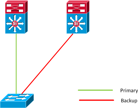
In
Figure 22-1,
ports 1 and 2 on switch A are connected to uplink switches B and C.
Because they are configured as Flex Links, only one of the interfaces is
forwarding traffic; the other is in standby mode. If port 1 is the
active link, it begins forwarding traffic between port 1 and switch B;
the link between port 2 (the backup link) and switch C is not forwarding
traffic. If port 1 goes down, port 2 comes up and starts forwarding
traffic to switch C. When port 1 comes back up, it goes into standby
mode and does not forward traffic; port 2 continues forwarding traffic.
You can also choose to configure a preemption
mechanism, specifying the preferred port for forwarding traffic. For
example, in the example in
Figure 22-1,
you can configure the Flex Links pair with preemption mode. In the
scenario shown, when port 1 comes back up and has more bandwidth than
port 2, port 1 begins forwarding traffic after 60 seconds. Port 2
becomes the standby port. You do this by entering the interface
configuration
switchport backup interface preemption mode bandwidth and
switchport backup interface preemption delay commands.
Figure 22-1 Flex Links Configuration Example
If a primary (forwarding) link goes down, a
trap notifies the network management stations. If the standby link goes
down, a trap notifies the users.
Flex Links are supported only on Layer 2 ports and port channels, not on VLANs or on Layer 3 ports.
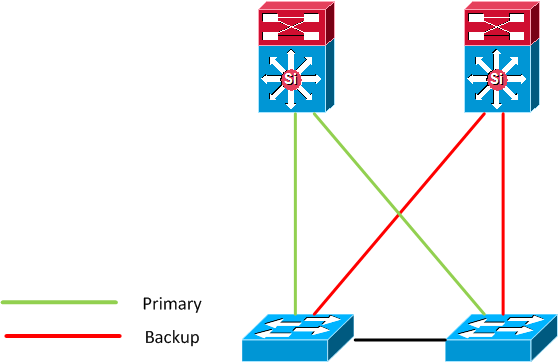
VLAN Flex Link Load Balancing and Support
VLAN Flex Link load-balancing allows you to
configure a Flex Link pair so that both ports simultaneously forward the
traffic for some mutually exclusive VLANs. For example, if Flex Link
ports are configured for 1-100 VLANs, the traffic of the first 50 VLANs
can be forwarded on one port and the rest on the other port. If one of
the ports fail, the other active port forwards all the traffic. When the
failed port comes back up, it resumes forwarding traffic in the
preferred VLANs. This way, apart from providing the redundancy, this
Flex Link pair can be used for load balancing. Also, Flex Link VLAN
load-balancing does not impose any restrictions on uplink switches.
Figure 22-2 VLAN Flex Links Load Balancing Configuration Example
Flex Link Multicast Fast Convergence
Flex Link Multicast Fast Convergence reduces
the multicast traffic convergence time after a Flex Link failure. This
is implemented by a combination of these solutions:
Learning the Other Flex Link Port as the mrouter Port
In a typical multicast network, there is a
querier for each VLAN. A switch deployed at the edge of a network has
one of its Flex Link ports receiving queries. Flex Link ports are also
always forwarding at any given time.
A port that receives queries is added as an mrouter
port on the switch. An mrouter port is part of all the multicast groups
learned by the switch. After a changeover, queries are received by the
other Flex Link port. The other Flex Link port is then learned as the
mrouter port. After changeover, multicast traffic then flows through the
other Flex Link port. To achieve faster convergence of traffic, both
Flex Link ports are learned as mrouter ports whenever either Flex Link
port is learned as the mrouter port. Both Flex Link ports are always
part of multicast groups.
Though both Flex Link ports are part of the
groups in normal operation mode, all traffic on the backup port is
blocked. So the normal multicast data flow is not affected by the
addition of the backup port as an mrouter port. When the changeover
happens, the backup port is unblocked, allowing the traffic to flow. In
this case, the upstream multicast data flows as soon as the backup port
is unblocked.
Generating IGMP Reports
When the backup link comes up after the
changeover, the upstream new distribution switch does not start
forwarding multicast data, because the port on the upstream router,
which is connected to the blocked Flex Link port, is not part of any
multicast group. The reports for the multicast groups were not forwarded
by the downstream switch because the backup link is blocked. The data
does not flow on this port, until it learns the multicast groups, which
occurs only after it receives reports.
The reports are sent by hosts when a general
query is received, and a general query is sent within 60 seconds in
normal scenarios. When the backup link starts forwarding, to achieve
faster convergence of multicast data, the downstream switch immediately
sends proxy reports for all the learned groups on this port without
waiting for a general query.
Leaking IGMP Reports
To achieve multicast traffic convergence with
minimal loss, a redundant data path must be set up before the Flex Link
active link goes down. This can be achieved by leaking only IGMP report
packets on the Flex Link backup link. These leaked IGMP report messages
are processed by upstream distribution routers, so multicast data
traffic gets forwarded to the backup interface. Because all incoming
traffic on the backup interface is dropped at the ingress of the access
switch, no duplicate multicast traffic is received by the host. When the
Flex Link active link fails, the access switch starts accepting traffic
from the backup link immediately. The only disadvantage of this scheme
is that it consumes bandwidth on the link between the distribution
switches and on the backup link between the distribution and access
switches. This feature is disabled by default and can be configured by
using the switchport backup interface interface-id multicast fast-convergence command.
When this feature has been enabled at
changeover, the switch does not generate the proxy reports on the backup
port, which became the forwarding port.
Configuration Examples
These are configuration examples for learning
the other Flex Link port as the mrouter port when Flex Link is
configured on Gigabit Ethernet1/0/11 and Gigabit Ethernet1/0/12, with
output for the show interfaces switchport backup command:
Switch# configure terminal
Enter configuration commands, one per line. End with CNTL/Z.
Switch(config)# interface gigabitehernet1/0/11
Switch(config-if)# switchport trunk encapsulation dot1q
Switch(config-if)# switchport mode trunk
Switch(config-if)# switchport backup interface gigabitehernet1/0/12
Switch(config)# interface gigabitehernet1/0/12
Switch(config-if)# switchport trunk encapsulation dot1q
Switch(config-if)# switchport mode trunk
Switch# show interfaces switchport backup detail
Switch Backup Interface Pairs:
Active Interface Backup Interface State
GigabitEthernet1/0/11 GigabitEthernet1/0/12 Active Up/Backup Standby
Multicast Fast Convergence : Off
Bandwidth : 100000 Kbit (Gi1/0/11), 100000 Kbit (Gi1/0/12)
Mac Address Move Update Vlan : auto
This output shows a querier for VLANs 1 and 401, with their queries reaching the switch through Gigabit Ethernet1/0/11:
Switch# show ip igmp snooping querier
Vlan IP Address IGMP Version Port
-------------------------------------------------------------
401 41.41.41.1 v2 Gi1/0/11
Here is output for the show ip igmp snooping mrouter command for VLANs 1 and 401:
Switch# show ip igmp snooping mrouter
1 Gi1/0/11(dynamic), Gi1/0/12(dynamic)
401 Gi1/0/11(dynamic), Gi1/0/12(dynamic)
Similarly, both Flex Link ports are part of learned groups. In this example, Gigabit Ethernet2/0/11 is a receiver/host in VLAN 1, which is interested in two multicast groups:
Switch# show ip igmp snooping groups
Vlan Group Type Version Port List
-----------------------------------------------------------------------
1 228.1.5.1 igmp v2 Gi1/0/11, Gi1/0/12, Gi2/0/11
1 228.1.5.2 igmp v2 Gi1/0/11, Gi1/0/12, Gi2/0/11
When a host responds to the general query, the switch forwards this report on all the mrouter ports. In this example, when a host sends a report for the group 228.1.5.1, it is forwarded only on Gigabit Ethernet1/0/11, because the backup port Gigabit Ethernet1/0/12 is blocked. When the active link, Gigabit Ethernet1/0/11, goes down, the backup port, Gigabit Ethernet1/0/12, begins forwarding.
As soon as this port starts forwarding, the switch sends proxy reports for the groups 228.1.5.1 and 228.1.5.2 on behalf of the host. The upstream router learns the groups and starts forwarding multicast data. This is the default behavior of Flex Link. This behavior changes when the user configures fast convergence using the switchport backup interface gigabitEthernet 1/0/12 multicast fast-convergence command. This example shows turning on this feature:
Switch# configure terminal
Enter configuration commands, one per line. End with CNTL/Z.
Switch(config)# interface gigabitethernet 1/0/11
Switch(config-if)# switchport backup interface gigabitethernet 1/0/12 multicast
fast-convergence
Switch# show interfaces switchport backup detail
Switch Backup Interface Pairs:
Active Interface Backup Interface State
------------------------------------------------------------------------
GigabitEthernet1/0/11 GigabitEthernet1/0/12 Active Up/Backup Standby
Multicast Fast Convergence : On
Bandwidth : 100000 Kbit (Gi1/0/11), 100000 Kbit (Gi1/0/12)
Mac Address Move Update Vlan : auto
This output shows a querier for VLAN 1 and 401 with their queries reaching the switch through Gigabit Ethernet1/0/11:
Switch# show ip igmp snooping querier
Vlan IP Address IGMP Version Port
-------------------------------------------------------------
401 41.41.41.1 v2 Gi1/0/11
This is output for the show ip igmp snooping mrouter command for VLAN 1 and 401:
Switch# show ip igmp snooping mrouter
1 Gi1/0/11(dynamic), Gi1/0/12(dynamic)
401 Gi1/0/11(dynamic), Gi1/0/12(dynamic)
Similarly, both the Flex Link ports are a part of the learned groups. In this example, Gigabit Ethernet2/0/11 is a receiver/host in VLAN 1, which is interested in two multicast groups:
Switch# show ip igmp snooping groups
Vlan Group Type Version Port List
-----------------------------------------------------------------------
1 228.1.5.1 igmp v2 Gi1/0/11, Gi1/0/12, Gi2/0/11
1 228.1.5.2 igmp v2 Gi1/0/11, Gi1/0/12, Gi2/0/11
Whenever a host responds to the general query, the switch forwards this report on all the mrouter ports. When you turn on this feature through the command-line port, and when a report is forwarded by the switch on GigabitEthernet1/0/11, it is also leaked to the backup port GigabitEthernet1/0/12. The upstream router learns the groups and starts forwarding multicast data, which is dropped at the ingress because GigabitEthernet1/0/12 is blocked. When the active link, GigabitEthernet1/0/11, goes down, the backup port, GigabitEthernet1/0/12, begins forwarding. You do not need to send any proxy reports because the multicast data is already being forwarded by the upstream router. By leaking reports to the backup port, a redundant multicast path has been set up, and the time taken for the multicast traffic convergence is minimal.
MAC Address-Table Move Update
The MAC address-table move update feature allows the switch to provide rapid bidirectional convergence when a primary (forwarding) link goes down and the standby link begins forwarding traffic.
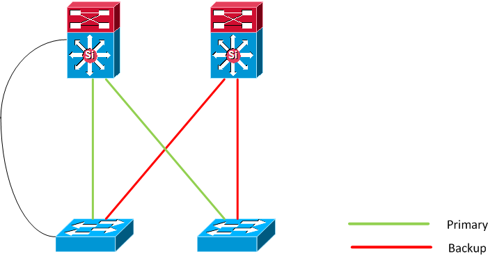
In
Figure 22-3, switch A is an access switch, and ports 1 and 2 on switch A are connected to uplink switches B and D through a Flex Link pair. Port 1 is forwarding traffic, and port 2 is in the backup state. Traffic from the PC to the server is forwarded from port 1 to port 3. The MAC address of the PC has been learned on port 3 of switch C. Traffic from the server to the PC is forwarded from port 3 to port 1.
If the MAC address-table move update feature is not configured and port 1 goes down, port 2 starts forwarding traffic. However, for a short time, switch C keeps forwarding traffic from the server to the PC through port 3, and the PC does not get the traffic because port 1 is down. If switch C removes the MAC address of the PC on port 3 and relearns it on port 4, traffic can then be forwarded from the server to the PC through port 2.
If the MAC address-table move update feature is configured and enabled on the switches in
Figure 22-3 and port 1 goes down, port 2 starts forwarding traffic from the PC to the server. The switch sends a MAC address-table move update packet from port 2. Switch C gets this packet on port 4 and immediately learns the MAC address of the PC on port 4, which reduces the reconvergence time.
You can configure the access switch, switch A, to send MAC address-table move update messages. You can also configure the uplink switches B, C, and D to get and process the MAC address-table move update messages. When switch C gets a MAC address-table move update message from switch A, switch C learns the MAC address of the PC on port 4. Switch C updates the MAC address table, including the forwarding table entry for the PC.
Switch A does not need to wait for the MAC address-table update. The switch detects a failure on port 1 and immediately starts forwarding server traffic from port 2, the new forwarding port. This change occurs in 100 milliseconds (ms). The PC is directly connected to switch A, and the connection status does not change. Switch A does not need to update the PC entry in the MAC address table.
Figure 22-3 MAC Address-Table Move Update Example
Configuring Flex Links and the MAC Address-Table Move Update
These sections contain this information:
Default Configuration
The Flex Links are not configured, and there are no backup interfaces defined.
The preemption mode is off.
The preemption delay is 35 seconds.
The MAC address-table move update feature is not configured on the switch.
Configuration Guidelines
Follow these guidelines to configure Flex Links:
•
You can configure up to 16 backup links.
•
You can configure only one Flex Link backup link for any active link, and it must be a different interface from the active interface.
•
An interface can belong to only one Flex Link pair. An interface can be a backup link for only one active link. An active link cannot belong to another Flex Link pair.
•
Neither of the links can be a port that belongs to an EtherChannel. However, you can configure two port channels (EtherChannel logical interfaces) as Flex Links, and you can configure a port channel and a physical interface as Flex Links, with either the port channel or the physical interface as the active link.
•
A backup link does not have to be the same type (Fast Ethernet, Gigabit Ethernet, or port channel) as the active link. However, you should configure both Flex Links with similar characteristics so that there are no loops or changes in behavior if the standby link begins to forward traffic.
•
STP is disabled on Flex Link ports. A Flex Link port does not participate in STP, even if the VLANs present on the port are configured for STP. When STP is not enabled, be sure that there are no loops in the configured topology. Once the Flex Link configurations are removed, STP is re-enabled on the ports.
Follow these guidelines to configure VLAN load balancing on the Flex Links feature:
•
For Flex Link VLAN load balancing, you must choose the preferred VLANs on the backup interface.
•
You cannot configure a preemption mechanism and VLAN load balancing for the same Flex Links pair.
Follow these guidelines to configure the MAC address-table move update feature:
•
You can enable and configure this feature on the access switch to
send the MAC address-table move updates.
•
You can enable and configure this feature on the uplink switches to
receive the MAC address-table move updates.
Configuring Flex Links
Beginning in privileged EXEC mode, follow these steps to configure a pair of Flex Links:
| |
Command
|
Purpose
|
Step 1
|
configure terminal
|
Enter global configuration mode.
|
Step 2
|
interface interface-id
|
Specify the interface, and enter interface configuration mode. The interface can be a physical Layer 2 interface or a port channel (logical interface). The port-channel range is 1 to 48.
|
Step 3
|
switchport backup interface interface-id
|
Configure a physical Layer 2 interface (or port channel) as part of a Flex Link pair with the interface. When one link is forwarding traffic, the other interface is in standby mode.
|
Step 4
|
end
|
Return to privileged EXEC mode.
|
Step 5
|
show interfaces [interface-id] switchport backup
|
Verify the configuration.
|
Step 6
|
copy running-config startup config
|
(Optional) Save your entries in the switch startup configuration file.
|
To disable a Flex Link backup interface, use the no switchport backup interface interface-id interface configuration command.
This example shows how to configure an interface with a backup interface and to verify the configuration:
Switch# configure terminal
Switch(conf)# interface gigabitethernet1/0/1
Switch(conf-if)# switchport backup interface gigabitethernet1/0/2
Switch# show interfaces switchport backup
Switch Backup Interface Pairs:
Active Interface Backup Interface State
------------------------------------------------------------------------
GigabitEthernet1/0/1 GigabitEthernet1/0/3 Active Standby/Backup Up
Vlans Preferred on Active Interface: 1-3,5-4094
Vlans Preferred on Backup Interface: 4
Beginning in privileged EXEC mode, follow these steps to configure a preemption scheme for a pair of Flex Links:
| |
Command
|
Purpose
|
Step 1
|
configure terminal
|
Enter global configuration mode.
|
Step 2
|
interface interface-id
|
Specify the interface, and enter interface configuration mode. The interface can be a physical Layer 2 interface or a port channel (logical interface). The port-channel range is 1 to 48.
|
Step 3
|
switchport backup interface interface-id
|
Configure a physical Layer 2 interface (or port channel) as part of a Flex Links pair with the interface. When one link is forwarding traffic, the other interface is in standby mode.
|
Step 4
|
switchport backup interface interface-id preemption mode [forced | bandwidth | off]
|
Configure a preemption mechanism and delay for a Flex Link interface pair. You can configure the preemption as:
• Forced—the active interface always preempts the backup.
• Bandwidth—the interface with the higher bandwidth always acts as the active interface.
• Off—no preemption happens from active to backup. |
Step 5
|
switchport backup interface interface-id preemption delay delay-time
|
Configure the time delay until a port preempts another port.
Note Setting a delay time only works with forced and bandwidth modes.
|
Step 6
|
end
|
Return to privileged EXEC mode.
|
Step 7
|
show interfaces [interface-id] switchport backup
|
Verify the configuration.
|
Step 8
|
copy running-config startup config
|
(Optional) Save your entries in the switch startup configuration file.
|
To remove a preemption scheme, use the no switchport backup interface interface-id preemption mode interface configuration command. To reset the delay time to the default, use the no switchport backup interface interface-id preemption delay interface configuration command.
This example shows how to configure the preemption mode as forced for a backup interface pair and to verify the configuration:
Switch# configure terminal
Switch(conf)# interface gigabitethernet1/0/1
Switch(conf-if)#switchport backup interface gigabitethernet1/0/2 preemption mode forced
Switch(conf-if)#switchport backup interface gigabitethernet1/0/2 preemption delay 50
Switch# show interfaces switchport backup detail
Active Interface Backup Interface State
------------------------------------------------------------------------
GigabitEthernet1/0/21 GigabitEthernet1/0/2 Active Up/Backup Standby
Interface Pair : Gi1/0/1, Gi1/0/2
Preemption Delay : 50 seconds
Bandwidth : 100000 Kbit (Gi1/0/1), 100000 Kbit (Gi1/0/2)
Mac Address Move Update Vlan : auto
Configuring VLAN Load Balancing on Flex Links
Beginning in privileged EXEC mode, follow these steps to configure VLAN load balancing on Flex Links:
| |
Command
|
Purpose
|
Step 1
|
configure terminal
|
Enter global configuration mode.
|
Step 2
|
interface interface-id
|
Specify the interface, and enter interface configuration mode. The interface can be a physical Layer 2 interface or a port channel (logical interface). The port-channel range is 1 to 48.
|
Step 3
|
switchport backup interface interface-id prefer vlan vlan-range
|
Configure a physical Layer 2 interface (or port channel) as part of a Flex Links pair with the interface, and specify the VLANs carried on the interface. The VLAN ID range is 1 to 4094.
|
Step 4
|
end
|
Return to privileged EXEC mode.
|
Step 5
|
show interfaces [interface-id] switchport backup
|
Verify the configuration.
|
Step 6
|
copy running-config startup config
|
(Optional) Save your entries in the switch startup configuration file.
|
To disable the VLAN load balancing feature, use the no switchport backup interface interface-id prefer vlan vlan-range interface configuration command.
In the following example, VLANs 1 to 50, 60, and 100 to 120 are configured on the switch:
Switch(config)#interface gigabitethernet 2/0/6
Switch(config-if)#switchport backup interface gigabitethernet 2/0/8 prefer vlan 60,100-120
When both interfaces are up, Gi2/0/8 forwards traffic for VLANs 60 and 100 to 120, and Gi2/0/6 forwards traffic for VLANs 1 to 50.
Switch#show interfaces switchport backup
Switch Backup Interface Pairs:
Active Interface Backup Interface State
------------------------------------------------------------------------
GigabitEthernet2/0/6 GigabitEthernet2/0/8 Active Up/Backup Up
Vlans Preferred on Active Interface: 1-50
Vlans Preferred on Backup Interface: 60, 100-120
When a Flex Link interface goes down (LINK_DOWN), VLANs preferred on this interface are moved to the peer interface of the Flex Link pair. In this example, if interface Gi2/0/6 goes down, Gi2/0/8 carries all VLANs of the Flex Link pair.
Switch#show interfaces switchport backup
Switch Backup Interface Pairs:
Active Interface Backup Interface State
------------------------------------------------------------------------
GigabitEthernet2/0/6 GigabitEthernet2/0/8 Active Down/Backup Up
Vlans Preferred on Active Interface: 1-50
Vlans Preferred on Backup Interface: 60, 100-120
When a Flex Link interface comes up, VLANs preferred on this interface are blocked on the peer interface and moved to the forwarding state on the interface that has just come up. In this example, if interface Gi2/0/6 comes up, VLANs preferred on this interface are blocked on the peer interface Gi2/0/8 and forwarded on Gi2/0/6.
Switch#show interfaces switchport backup
Switch Backup Interface Pairs:
Active Interface Backup Interface State
------------------------------------------------------------------------
GigabitEthernet2/0/6 GigabitEthernet2/0/8 Active Up/Backup Up
Vlans Preferred on Active Interface: 1-50
Vlans Preferred on Backup Interface: 60, 100-120
Switch#show interfaces switchport backup detail
Switch Backup Interface Pairs:
Active Interface Backup Interface State
------------------------------------------------------------------------
GigabitEthernet1/0/3 GigabitEthernet1/0/4 Active Down/Backup Up
Vlans Preferred on Active Interface: 1-2,5-4094
Vlans Preferred on Backup Interface: 3-4
Bandwidth : 10000 Kbit (Gi1/0/3), 100000 Kbit (Gi1/0/4)
Mac Address Move Update Vlan : auto
Configuring the MAC Address-Table Move Update Feature
This section contains this information:
•
Configuring a switch to send MAC address-table move updates
•
Configuring a switch to get MAC address-table move updates
Beginning in privileged EXEC mode, follow these steps to configure an access switch to send MAC address-table move updates:
| |
Command
|
Purpose
|
Step 1
|
configure terminal
|
Enter global configuration mode.
|
Step 2
|
interface interface-id
|
Specify the interface, and enter interface configuration mode. The interface can be a physical Layer 2 interface or a port channel (logical interface). The port-channel range is 1 to 48.
|
Step 3
|
switchport backup interface interface-id
or
switchport backup interface interface-id mmu primary vlan vlan-id
|
Configure a physical Layer 2 interface (or port channel), as part of a Flex Link pair with the interface. The MAC address-table move update VLAN is the lowest VLAN ID on the interface.
Configure a physical Layer 2 interface (or port channel) and specify the VLAN ID on the interface, which is used for sending the MAC address-table move update.
When one link is forwarding traffic, the other interface is in standby mode.
|
Step 4
|
end
|
Return to global configuration mode.
|
Step 5
|
mac address-table move update transmit
|
Enable the access switch to send MAC address-table move updates to other switches in the network if the primary link goes down and the switch starts forwarding traffic through the standby link.
|
Step 6
|
end
|
Return to privileged EXEC mode.
|
Step 7
|
show mac address-table move update
|
Verify the configuration.
|
Step 8
|
copy running-config startup config
|
(Optional) Save your entries in the switch startup configuration file.
|
To disable the MAC address-table move update feature, use the no mac address-table move update transmit interface configuration command. To display the MAC address-table move update information, use the show mac address-table move update privileged EXEC command.
This example shows how to configure an access switch to send MAC address-table move update messages:
Switch(conf)# interface gigabitethernet1/0/1
Switch(conf-if)# switchport backup interface gigabitethernet1/0/2 mmu primary vlan 2
Switch(conf)# mac address-table move update transmit
This example shows how to verify the configuration:
Switch# show mac-address-table move update
Switch-ID : 010b.4630.1780
Dst mac-address : 0180.c200.0010
Vlans/Macs supported : 1023/8320
Default/Current settings: Rcv Off/On, Xmt Off/On
Max packets per min : Rcv 40, Xmt 60
Rcv conforming packet count : 5
Rcv invalid packet count : 0
Rcv packet count this min : 0
Rcv threshold exceed count : 0
Rcv last sequence# this min : 0
Rcv last src-mac-address : 000b.462d.c502
Rcv last switch-ID : 0403.fd6a.8700
Xmt packet count this min : 0
Xmt threshold exceed count : 0
Xmt pak buf unavail cnt : 0
Xmt last interface : None
Beginning in privileged EXEC mode, follow these steps to configure a switch to get and process MAC address-table move update messages:
| |
Command
|
Purpose
|
Step 1
|
configure terminal
|
Enter global configuration mode.
|
Step 2
|
mac address-table move update receive
|
Enable the switch to get and process the MAC address-table move updates.
|
Step 3
|
end
|
Return to privileged EXEC mode.
|
Step 4
|
show mac address-table move update
|
Verify the configuration.
|
Step 5
|
copy running-config startup config
|
(Optional) Save your entries in the switch startup configuration file.
|
To disable the MAC address-table move update feature, use the no mac address-table move update receive configuration command. To display the MAC address-table move update information, use the show mac address-table move update privileged EXEC command.
This example shows how to configure a switch to get and process MAC address-table move update messages:
Switch# configure terminal
Switch(conf)# mac address-table move update receive
Monitoring Flex Links and the MAC Address-Table Move Update
Table 22-1 shows the privileged EXEC commands for monitoring the Flex Links configuration and the MAC address-table move update information.
Table 22-1 Flex Links and MAC Address-Table Move Update Monitoring Commands
|
Command
|
Purpose
|
show interfaces [interface-id] switchport backup
|
Displays the Flex Link backup interface configured for an interface or all the configured Flex Links and the state of each active and backup interface (up or standby mode). When VLAN load balancing is enabled, the output displays the preferred VLANS on Active and Backup interfaces.
|
show mac address-table move update
|
Displays the MAC address-table move update information on the switch.
|