Thursday 3 March 2016

OSPF NSSA

Introduction

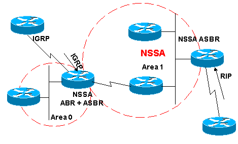
The OSPF not-so-stubby area (NSSA) feature is described by RFC 1587 leavingcisco.com and is first introduced in Cisco IOS® Software release 11.2. It is a non-proprietary extension of the existing stub area feature that allows the injection of external routes in a limited fashion into the stub area. This document explains how the NSSA feature works.
Redistribution into an NSSA area creates a special type of link-state advertisement (LSA) known as type 7, which can only exist in an NSSA area. An NSSA autonomous system boundary router (ASBR) generates this LSA and an NSSA area border router (ABR) translates it into a type 5 LSA, which gets propagated into the OSPF domain. The network diagram demonstrates this principle.

Prerequisites

Requirements

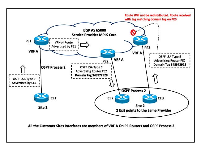
Refer to this network diagram as you use this document:
nssa.gif
In the network diagram, Area 1 is defined as a stub area. IGRP routes cannot be propagated into the OSPF domain because redistribution is not allowed in the stub area. However, if we define Area 1 as NSSA, we can inject IGRP routes into the OSPF NSSA domain with the creation of type 7 LSAs. Redistributed RIP routes are not allowed in Area 1 because NSSA is an extension to the stub area. The stub area characteristics still exist, which includes no type 5 LSAs allowed.

Components Used

This document is not restricted to specific software and hardware versions.
The information presented in this document was created from devices in a specific lab environment. All of the devices used in this document started with a cleared (default) configuration. If you are working in a live network, ensure that you understand the potential impact of any command before using it.

What Is a Type 7 LSA?

This is a type 7 LSA that is generated by an NSSA ASBR. Type 5 LSAs are not allowed in NSSA areas, so the NSSA ASBR generates a type 7 LSA instead, which remains within the NSSA. This type 7 LSA gets translated back into a type 5 by the NSSA ABR.
LS age: 36
  Options: (No TOS-capability, No Type 7/5 translation, DC)
  LS Type: AS External Link
  Link State ID: 10.10.10.0 (External Network Number)
  Advertising Router: 141.108.1.21
  LS Seq Number: 80000001
  Checksum: 0x4309
  Length: 36
  Network Mask: /24
        Metric Type: 2 (Larger than any link state path)
        TOS: 0 
        Metric: 20 
        Forward Address: 9.9.9.9
        External Route Tag: 0
This output looks similar to an external LSA. These are some important characteristics about this output:
  • Bit P—This bit is used in order to tell the NSSA ABR whether to translate type 7 into type 5.
  • No Type 7/5 translation means bit P = 0.
  • Type 7/5 translation means bit P = 1.
  • If bit P = 0, then the NSSA ABR must not translate this LSA into Type 5. This happens when NSSA ASBR is also an NSSA ABR.
  • If bit P = 1, then the NSSA ABR must translate this type 7 LSA into a type 5 LSA. If there are multiple NSSA ABRs, the one with highest router ID.

Configuration Tasks

There are two flavors in NSSA, just like in stub areas. There are NSSAs that block type 5 and type 4 LSAs, but allow type 3 LSAs, and there are NSSA totally stub areas, which allow only summary default routes and filters everything else.

Defining a Not-So-Stubby Area

In order to make a stub area into an NSSA, issue this command under the OSPF configuration:
router ospf 1
 Area 1 nssa
This command must be configured on every single router in Area 1. After you define Area 1 as an NSSA, it must have these characteristics:
  • No Type 5 LSAs are allowed in Area 1. This means no RIP routes are allowed in Area 1.
  • All IGRP routes are redistributed as type 7. This type 7 can only exist within NSSA.
  • All type 7 LSAs are translated into type 5 LSAs by the NSSA ABR and are leaked into the OSPF domain as type 5 LSAs.

Defining an NSSA Totally Stub Area

In order to configure an NSSA totally stub area, issue this command under the OSPF configuration:
router ospf 1
 Area 1 nssa no-summary
Configure this command on NSSA ABRs only. After you define the NSSA totally stub area, Area 1 has these characteristics in addition to the NSSA characteristics:
  • No type 3 or 4 summary LSAs are allowed in Area 1. This means no inter-area routes are allowed in Area 1.
  • A default route is injected into the NSSA totally stub area as a type 3 summary LSA.

Filtering in NSSA

There are situations where there is no need to inject external routes into the NSSA as type 7. This situation usually occurs when an ASBR is also an NSSA ABR. When redistribution takes place in this scenario, the router generates type 5 as well as type 7 LSAs. You can prevent the router from creating type 7 LSAs for NSSA with this command:
router ospf 1
 Area 1 nssa no-redistribution
In the network diagram, Area 1 is configured with the no-redistribution option. This means that all IGRP routes are redistributed into area 0, but no type 7 LSAs are generated for Area 1. Only configure this command on an NSSA ASBR that is also an ABR.
nssa1.gif
Another case of filtering is when you need to prevent the type 7 LSAs from being translated outside the NSSA. In other words, when you want to control which type 7 LSAs get translated into type 5. For example, you have a RIP learned route 141.108.10.0/24 that is injected into the OSPF NSSA Area 1. You do not want this route to be leaked into the rest of the OSPF areas. Use this configuration on either the NSSA ASBR or the NSSA ABR in order to accomplish this:
router ospf 1
 summary-address 141.108.10.0 255.255.255.0 not-advertise
This configuration generates a type 7 LSA that is not translated into type 5 by the NSSA ABR.

Default Route in NSSA

There are two ways to have a default route in an NSSA. When you configure an area as NSSA, by default the NSSA ABR does not generate a default summary route. In the case of a stub area or an NSSA totally stub area, the NSSA ABR does generate a default summary route.

Default Summary Route

By defining an area as a NSSA totally stub area, the NSSA ABR generates a default summary route. As mentioned, if the NSSA area were not defined as totally stub, then a default summary route is not generated by NSSA ABR. This configuration generates a default summary route for a NSSA totally stub area.
router ospf 1
 Area 1 nssa no-summary

Default Type 7

This configuration generates a type 7 default route. You can configure this command on any NSSA ASBR or NSSA ABR with these rules:
  • NSSA ASBR can generate a default only when it has a default route in its routing table.
  • The default route must be known through non-OSPF protocol
  • NSSA ABR can generate a default route with or without a default route in its own routing table.
This command is used in order to generate an NSSA default route:
router ospf 1
 Area 1 nssa default-information-originate

OSPF down bit set

OSPF--Down Bit

I’ve seen the same question in several blogs, so today I will try to turn this subject inside-out.
Let’s focus on the following scenario:
The following sequence takes place, which can lead to a potential routing loop:
  1. R2 sends an LSA1 or LSA2 to PE1
  2. PE1 receives the intra-area OSPF route from R2 and redistributes it into MP-BGP.
  3. The receiving PE router, let’s say PE2, redistributes the MP-BGP route into OSPF as an LSA3 (remember that MPLS backbone acts as an OSPF superbackbone)
  4. LSA3 is propagated across the OSPF area and received by the other PE router, PE3 in our diagram, which is attached to the same OSPF area 1.
  5. Because PE3 has the same route learned by two protocols (OSPF and MP-BGP), it has to make a decision based on the administrative distance. Because the administrative distance of OSPF is better than the administrative distance of MP-iBGP, it selects the OSPF route. Therefore, PE3 redistributes the route OSPF back into the MP-BGP process, potentially resulting in a routing loop.
This is why it’s completely necessary to have a mechanism to break the loop, and OSPF down bit is that mechanism.
The down bit  is a bit located in the LSA Header, and its function is to avoid loops in MPLS-VPN environments when using OSPF as PE-CE protocol.


When PE2 redistributes the MP-BGP route into OSPF, it sets up the down bit, or downward, on the LSA3. So when PE3 receives that LSA3, it doesn’t take it into account.
R1#sh ip ospf datab

            OSPF Router with ID (1.1.1.1) (Process ID 100)
  Router Link States (Area 1)

Link ID         ADV Router      Age         Seq#       Checksum Link count
1.1.1.1         1.1.1.1         690         0x8000000D 0x007847 5
103.103.103.3   103.103.103.3   879         0x80000009 0x006DEE 2
200.200.200.2   200.200.200.2   1040        0x8000000A 0x00789F 2

  Summary Net Link States (Area 1)

Link ID         ADV Router      Age         Seq#       Checksum
2.2.2.2         103.103.103.3   108         0x80000001 0x00F583
2.2.2.2         200.200.200.2   108         0x80000001 0x00DA7B
10.10.22.0      103.103.103.3   98          0x80000001 0x005AFD
10.10.22.0      200.200.200.2   98          0x80000001 0x003FF5

R1#
R1#sh ip ospf databa summ 2.2.2.2

            OSPF Router with ID (1.1.1.1) (Process ID 100)
  Summary Net Link States (Area 1)

  Routing Bit Set on this LSA in topology Base with MTID 0
  LS age: 133
  Options: (No TOS-capability, DC, Downward)
  LS Type: Summary Links(Network)
  Link State ID: 2.2.2.2 (summary Network Number)
  Advertising Router: 103.103.103.3
  ...

  Routing Bit Set on this LSA in topology Base with MTID 0
  LS age: 133
  Options: (No TOS-capability, DC, Downward)
  LS Type: Summary Links(Network)
  Link State ID: 2.2.2.2 (summary Network Number)
  Advertising Router: 200.200.200.2
R1#
PE3#sh ip ospf 100 databa
            OSPF Router with ID (103.103.103.3) (Process ID 100)
  Router Link States (Area 1)

Link ID         ADV Router      Age         Seq#       Checksum Link count
1.1.1.1         1.1.1.1         649         0x8000000D 0x007847 5
103.103.103.3   103.103.103.3   836         0x80000009 0x006DEE 2
200.200.200.2   200.200.200.2   1000        0x8000000A 0x00789F 2

  Summary Net Link States (Area 1)

Link ID         ADV Router      Age         Seq#       Checksum
2.2.2.2         103.103.103.3   65          0x80000001 0x00F583
2.2.2.2         200.200.200.2   67          0x80000001 0x00DA7B
10.10.22.0      103.103.103.3   55          0x80000001 0x005AFD
10.10.22.0      200.200.200.2   57          0x80000001 0x003FF5
PE3#
PE3#sh ip ospf databa summ 2.2.2.2

            OSPF Router with ID (103.103.103.3) (Process ID 100)
  Summary Net Link States (Area 1)

  LS age: 146
  Options: (No TOS-capability, DC, Downward)
  LS Type: Summary Links(Network)
  Link State ID: 2.2.2.2 (summary Network Number)
  Advertising Router: 103.103.103.3
  ...

  LS age: 148
  Options: (No TOS-capability, DC, Downward)
  LS Type: Summary Links(Network)
  Link State ID: 2.2.2.2 (summary Network Number)
  Advertising Router: 200.200.200.2
  ...
PE3#
This down bit is present only in the LSA3. LSA5 and LSA7 doesnt have this bit in its headers.
Let’s check this statement making PE2 and PE3 redistribute the route as LSA5. In order to do that, I will change the ospf-domain in PE1:
PE1#conf term
PE1(config)#router ospf 100
PE1(config-router)#domain-id 1.1.1.1
PE1(config-router)#end
PE1#
R1#sh ip ospf data
            OSPF Router with ID (1.1.1.1) (Process ID 100)
  Router Link States (Area 1)

Link ID         ADV Router      Age         Seq#       Checksum Link count
1.1.1.1         1.1.1.1         898         0x8000000D 0x007847 5
103.103.103.3   103.103.103.3   1087        0x80000009 0x006DEE 2
200.200.200.2   200.200.200.2   1249        0x8000000A 0x00789F 2

  Type-5 AS External Link States

Link ID         ADV Router      Age         Seq#       Checksum Tag
2.2.2.2         103.103.103.3   56          0x80000001 0x009F19 3489725929
2.2.2.2         200.200.200.2   56          0x80000001 0x008411 3489725929
10.10.22.0      103.103.103.3   66          0x80000001 0x000493 3489725929
10.10.22.0      200.200.200.2   66          0x80000001 0x00E88B 3489725929
R1#
R1#sh ip ospf databa extern 2.2.2.2

            OSPF Router with ID (1.1.1.1) (Process ID 100)
  Type-5 AS External Link States

  Routing Bit Set on this LSA in topology Base with MTID 0
  LS age: 64
  Options: (No TOS-capability, DC)
  LS Type: AS External Link
  Link State ID: 2.2.2.2 (External Network Number )
  Advertising Router: 103.103.103.3
  ...

  Routing Bit Set on this LSA in topology Base with MTID 0
  LS age: 64
  Options: (No TOS-capability, DC)
  LS Type: AS External Link
  Link State ID: 2.2.2.2 (External Network Number )
  Advertising Router: 200.200.200.2
  ...
R1#
PE3#sh ip ospf 100 datab
            OSPF Router with ID (103.103.103.3) (Process ID 100)
  Router Link States (Area 1)

Link ID         ADV Router      Age         Seq#       Checksum Link count
1.1.1.1         1.1.1.1         851         0x8000000D 0x007847 5
103.103.103.3   103.103.103.3   1038        0x80000009 0x006DEE 2
200.200.200.2   200.200.200.2   1202        0x8000000A 0x00789F 2

  Type-5 AS External Link States
Link ID         ADV Router      Age         Seq#       Checksum Tag
2.2.2.2         103.103.103.3   7           0x80000001 0x009F19 3489725929
2.2.2.2         200.200.200.2   9           0x80000001 0x008411 3489725929
10.10.22.0      103.103.103.3   17          0x80000001 0x000493 3489725929
10.10.22.0      200.200.200.2   19          0x80000001 0x00E88B 3489725929
PE3#
PE3#sh ip ospf 100 databa extern 2.2.2.2

            OSPF Router with ID (103.103.103.3) (Process ID 100)
  Type-5 AS External Link States

  LS age: 30
  Options: (No TOS-capability, DC)
  LS Type: AS External Link
  Link State ID: 2.2.2.2 (External Network Number )
  Advertising Router: 103.103.103.3
  ...

  LS age: 32
  Options: (No TOS-capability, DC)
  LS Type: AS External Link
  Link State ID: 2.2.2.2 (External Network Number )
  Advertising Router: 200.200.200.2
  ...
PE3#
In order to check if LSA7 has this bit, I change the area type and redistribution in PE2 and PE3:
PE2(config)#router ospf 100
PE2(config-router)#redis bgp 65001 sub nssa-only
PE2(config-router)#area 1 nssa
PE2(config-router)#end
PE2#
PE3(config)#router ospf 100
PE3(config-router)#redis bgp 65001 sub nssa-only
PE3(config-router)#area 1 nssa
PE3(config-router)#end
PE3#
R1#sh ip ospf databa

            OSPF Router with ID (1.1.1.1) (Process ID 100)
  Router Link States (Area 1)

Link ID         ADV Router      Age         Seq#       Checksum Link count
1.1.1.1         1.1.1.1         75          0x80000010 0x00189E 5
103.103.103.3   103.103.103.3   80          0x8000000B 0x000F45 2
200.200.200.2   200.200.200.2   80          0x8000000C 0x001AF5 2

  Type-7 AS External Link States (Area 1)

Link ID         ADV Router      Age         Seq#       Checksum Tag
2.2.2.2         103.103.103.3   10          0x80000001 0x003E54 3489725929
2.2.2.2         200.200.200.2   10          0x80000001 0x000869 3489725929
10.10.22.0      103.103.103.3   223         0x80000002 0x00A0CF 3489725929
10.10.22.0      200.200.200.2   190         0x80000001 0x006CE3 3489725929
R1#
R1#sh ip ospf datab nssa-external 2.2.2.2

            OSPF Router with ID (1.1.1.1) (Process ID 100)
  Type-7 AS External Link States (Area 1)

  Routing Bit Set on this LSA in topology Base with MTID 0
  LS age: 28
  Options: (No TOS-capability, No Type 7/5 translation, DC)
  LS Type: AS External Link
  Link State ID: 2.2.2.2 (External Network Number )
  Advertising Router: 103.103.103.3
  ...

  Routing Bit Set on this LSA in topology Base with MTID 0
  LS age: 28
  Options: (No TOS-capability, No Type 7/5 translation, DC)
  LS Type: AS External Link
  Link State ID: 2.2.2.2 (External Network Number )
  Advertising Router: 200.200.200.2
  ...
R1#
The down bit helps prevent routing loops between MP-BGP and OSPF when LSA3 are used, but not when external routes are announced.
So then, how are routing loops avoided when external routes are present? Well, with LSA5 and LSA7 there is a new field checked to avoid loops. This is called the tag field:
PE3#sh ip ospf 100 datab
            OSPF Router with ID (103.103.103.3) (Process ID 100)
                Router Link States (Area 1)

Link ID         ADV Router      Age         Seq#       Checksum Link count
1.1.1.1         1.1.1.1         834         0x80000010 0x00189E 5
103.103.103.3   103.103.103.3   837         0x8000000B 0x000F45 2
200.200.200.2   200.200.200.2   839         0x8000000C 0x001AF5 2

                Type-7 AS External Link States (Area 1)

Link ID         ADV Router      Age         Seq#       Checksum Tag
2.2.2.2         103.103.103.3   19          0x80000001 0x003E54 3489725929
2.2.2.2         200.200.200.2   11          0x80000004 0x00026C 3489725929
10.10.22.0      103.103.103.3   19          0x80000001 0x00A2CE 3489725929
10.10.22.0      200.200.200.2   11          0x80000004 0x0066E6 3489725929
When a PE redistributes a route from MP-BGP into OSPF as LSA5 or LSA7, it adds a tag to the route (tag 3989725929 by default). So if another PE receives an LSA5 or LSA7 with this tag, it doesn’t redistribute it back into MP-BGP: Of course, we may change the value of the tag to any other value. This is done when configuring the redistribution under ospf process:
PE2#conf term
PE2(config)#router ospf 100
PE2(config-router)# redistribute bgp 65001 subnets tag 100
PE2(config-router)#end
PE2#

OSPF as PE-CE Protocol and Loop-Prevention Techniques in MPLS L3 VPN Configuration Example down bit set

Introduction

This document describes the loop prevention features and the minimum configuration steps when you run the Open Shortest Path First (OSPF) Routing Protocol between Provider Edge (PE) and Customer Edge (CE) Routers. It presents a network scenario that depicts the use of Downward Bit (DN), which is an option in the Link State Advertisement (LSA) and Domain Tag.

Prerequisites


Requirements

Cisco recommends that you have knowledge of OSPF and Multiprotocol Label Switching (MPLS) Layer 3 VPN.

Components Used

This document is not restricted to specific software and hardware versions.
The information in this document was created from the devices in a specific lab environment. All of the devices used in this document started with a cleared (default) configuration. If your network is live, make sure that you understand the potential impact of any command.

Background Information

The Service Provider (SP) and the CE Router exchange routes with a routing protocol to which the SP and and Customer jointly agree. The scope of this document is to describe the loop-prevention mechanism when OSPFv2 is used.
When OSPFv2 is used on a PE-CE link that belongs to a particular Virtual Routing and Forwarding (VRF) or VPN, the PE router:
  • Redistributes the routes received via OSPF for that VPN into Multiprotocol-Border Gateway Protocol (MP-BGP) and advertises it to the other PE routers.
  • Redistributes the BGP routes intalled in the VPN via MP-BGP into the OSPF Instance for that VPN and advertises it to the CE Routers.

Configure


Network Diagram

Consider this network topology in order to understand the loop-prevention techniques.

In this setup, there is a possibility of a loop. For example, if CE1 advertises the OSPF LSA Type 1 to PE1, which redistributes the route into VPNv4 and advertises it to PE2, then PE2 in turn advertises the Summary LSA to CE2. This route received by CE2 could be advertised back to PE3. The third PE router learns the OSPF route, which is better than the BGP route, and re-advertises the route into BGP as local to the Customer Site 2. PE3 never learns that the route that was advertised was not originated from Customer Site 2.
In order to overcome this situation, when the routes are redistributed from MP-BGP into OSPF, then they are marked with a DN Bit in LSA Type 3, 5, or 7 and have the domain tag for Type 5 and 7 LSA.

Configurations

Here is the sample configuration on PE routers. This configuration includes the VRF configuration, the OSPF Process 2 that runs between the PE-CE Routers, the OSPF Process 1 that runs as Interior Gateway Protocol ( IGP) in the MPLS Core, and the MP-BGP configuration.


DN Bit

The previously unused bit in the OSPF LSA Options Field is referred to as the DN Bit. This bit is set on Type 3, 5, and 7 LSA when the MP-BGP routes are redistributed into OSPF. When the other PE Router receives the LSA from a CE router Type 3, 5, or 7 LSA with the DN Bit set, the information from that LSA is not used in the OSPF route calculation.

Based on the network topology, PE2 sets the DN Bit for the redistributed LSA and this LSA is never considered for route calculation in OSPF Process 2 on PE3. So PE3 never redistributes this route back into MP-BGP.
Here is an example of the OSPF Header that shows the DN Bit Set, when the route was advertised by PE Router for Type 3 LSA:
Open Shortest Path First
    OSPF Header
        Version: 2
        Message Type: LS Update (4)
        Packet Length: 56
        Source OSPF Router: 10.10.23.3 (10.10.23.3)
        Area ID: 0.0.0.0 (0.0.0.0) (Backbone)
        Checksum: 0x4034 [correct]
        Auth Type: Null (0)
        Auth Data (none): 0000000000000000
    LS Update Packet
        Number of LSAs: 1
        Summary-LSA (IP network)
            .000 1110 0001 0000 = LS Age (seconds): 3600
            0... .... .... .... = Do Not Age Flag: 0
            Options: 0xa2 (DN, DC, E)
                1... .... = DN: Set
                .0.. .... = O: Not set
                ..1. .... = DC: Demand Circuits are supported
                ...0 .... = L: The packet does NOT contain LLS data block
                .... 0... = NP: NSSA is NOT supported
                .... .0.. = MC: NOT Multicast Capable
                .... ..1. = E: External Routing Capability
                .... ...0 = MT: NO Multi-Topology Routing

Domain Tag

The Domain Tag is applicable only for the OSPF Type 5 and Type 7 LSA. When the VPNv4 routes are redistributed from MP-BGP into OSPF on PE Router, the Domain Tag is set for OSPF External Routes. The tag could either be manuallly set with the domain-tag command under OSPF Process or a 32-bit value can be automatically generated:


Based on the network topology, PE2 sets the Domain Tag for Type 5 and Type 7 LSA when it redistributes the VPNv4 route into OSPF. This LSA is never considered for route calculation because the DN Bit is already set, but it also has the Domain Tag set, so the LSA is ignored because the Domain Tag matches the VPN / VRF Tag. Hence the route is never redistributed into OSPF.
This example shows LSA Type 5 ignored when it is received with the Domain Tag Set the same as the local VRF Domain Tag on PE3 from CE3:
*Jan 31 00:29:23.947: OSPF-2 EXTER:  adv_rtr 10.10.57.5, age 3, seq 0x80000001, 
metric 10, metric-type 2, fw-addr 0.0.0.0
*Jan 31 00:29:23.947: OSPF-2 EXTER: Tag equals to VPN Tag, ignoring the LSA
*Jan 31 00:29:23.947: OSPF-2 EXTER: Process partial nssa spf queue

PE3#show ip ospf database external 192.168.5.5

            OSPF Router with ID (10.3.3.3) (Process ID 1)

            OSPF Router with ID (10.10.68.6) (Process ID 2)

                Type-5 AS External Link States

  LS age: 38
  Options: (No TOS-capability, DC)
  LS Type: AS External Link
  Link State ID: 192.168.5.5 (External Network Number )
  Advertising Router: 10.10.57.5
  LS Seq Number: 80000001
  Checksum: 0x89A3
  Length: 36
  Network Mask: /32
        Metric Type: 2 (Larger than any link state path)
        MTID: 0
        Metric: 10
        Forward Address: 0.0.0.0
        External Route Tag: 3489725928

Verify

The commands to discover if the DN Bit is set for the LSA and the Domain Tag applied are the same that are used in order to check the LSA Database.
This output shows the example for OSPF Type 3 and Type 5 LSA and highlights the DN Bit and Tag Set when the VPNv4 routes are redistributed into OSPF on PE2:

 Note: MPLS VPN OSPF PE-CE always includes the loop-prevention mechanism in order to handle issues. In the older Cisco IOS®, the Per original IETF draft Type 3 LSAs use the DN Bit in LSA and Type 5 LSAs use a tag. The newer RFC 4576 mandates use of DN Bit for both Type 3 and Type 5 LSAs.

This was committed via Cisco bug ID CSCtw79182.

The PE routers with Cisco IOS images with the fix of this defect will originate Type 5 external LSAs with both DN Bit and a tag as loop-prevention mechanisms. Previous Cisco IOS versions advertised the only tag for this purpose for External Routes.

The change in behavior was made because a tag is possible to rewrite (by changing VPN domain ID or via route-map) but the DN Bit is not user-controllable. In some corner-case designs, some customers might have deliberately disabled the loop-prevention mechanism with an overwrite of tags of external LSAs in order for the PE router to prefer the OSPF route over the BGP route.

In newer Cisco IOS versions, this is not possible. The vast majority of customers that use PE-CE OSPF in a textbook configuration will not be affected. Customers that override tags MIGHT see a change in behavior.


THE DOWN BIT                                                                       _________________                 
consider                                                        /                                  \
                                                                    /                                      \ 
  CE------\-PE1---------------PE2------------/--CE2                                    |
                                            |                       |                 ospf domain   |
                                           |                       |                                     /  
                                        PE 2.1---------/--CE2.1                                /   
                                                                       \__________________/

when the router CE advertise a route to PE1, the route gets redistributed into mpbgp, and
when PE2 receives it, its redistributed into ospf domain, and at PE2.1 the same ospf route
is again redistributed into mpbgp, and this causes a loop

>> to save this problem, a DOWN BIT is defined in the OSPF LSA, and this bit is set whenever a MPBGP route is redistributed into ospf domain, and the PE router never redistributes a OSPF route with DOWN bit set to MPBGP, therefore essentially preventing the loop.
>> THE ROUTING BIT IS NOT SET ON ROUTES WITH DOWN BIT SET. AND THIS ROUTING BIT IS USED INTERNALLY AND IS NOT PROPAGATED IN UPDATES AND THESE ROUTES NEVER ENTER THE ROUTING TABLE.
>> Also the  DOWN bit is cleared when the route is adverised out a ospf domain to different ospf domain. so, there are chances this same route gets redistributed into the mpbgp and CAUSING A LOOP , at somewhere else, so, therefore to prevent this ROUTE-TAGS are used.


.>>how tags work
when the PE router redistributes the mpbgp route into ospf, in addition to setting the down bit, it also adds a TAG value equal to the BGP AS no, to that route, now after the route has been redistributed into the ospf domain, with down bit set and the tag value put, and if this route now is advertised to a different ospf domain, as en external route ofcourse, the down bit will be removed but the tag is carried along, and when this route comes to the PE in that domain to get redistributed into the mPbgp the PE router checks the tag, value, if the tag value is same as the BgpAS no then the route is no redistributed

some people mentioned

Both the OSPF (Down-Bit) and (Domain-Tag) Prevents OSPF routing loop. Although these features may look Same but there is a Major different implementation Scenario where the (Down-Bit) wont prevent loop and the (Domain-Tag) would be the right choice.

Here is the difference:

Down-Bit :-   The (Down-Bit) is an Option in the LSA Header, its set whenever the Route is redistributed from MPBGP to OSPF, It ensures the same route is never back to the same OSPF Source originating it. In a Dual Homed Scenario to the Same MPLS Provider, the CE might send the same route back to the provider and without the (Down-Bit) Option , A Loop woud Occur.

However,  The (Down-Bit) Option  will not prevent a Loop incase the Route traverse more than a Single MPLS Provider. Meaning, if there is a CE dual homed to Two different  MPLS Service Providers , and those Providers are interconnected using (Inter-as) Architecture Approach, the Down-Bit Will not Prevent the Loop.  Here came the Need for (OSPF Domain-Tag) where this Option is primarily used in such situation to ensure the OSPF domain-Tag is preserved unique a cross different ***.  So whenever the route is back by different AS , the Original MPLS Provider which source the update reject the route since the (Domain-Tag) feature is set.