Control plane and Forwarding plane
A collection of processes that run at the process level on the route-processor (RP). These processes collectively provide high-level controls for most IOS functions.
The control plane in general is anything that’s needed in order to get routing working on that device; in other words, it is the “signalling” of the network. Control plane packets are destined to or locally originated by the router itself.
Examples of control plane protocols are CDP, BPDUs, Routing Protocols (OSPF, RIP, EIGRP, BGP,IS-IS)
There are methods to police traffic meant to the control plane(i.e. CoPP Control Plane Policing)
Forwarding Plane/Data Plane -
Moves packets from input to output, defines the part of the router architecture that decides what to do with packets arriving on an inbound interface. Most commonly, it refers to a table in which the router looks up the destination address of the incoming packet and retrieves the information necessary to determine the path from the receiving element, through the internal forwarding fabric of the router, and to the proper outgoing interface.


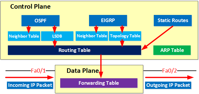
Diagram to show interaction between control plane and data plane.
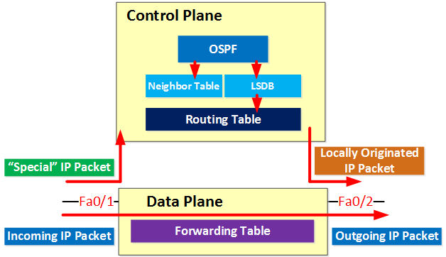
- IP packets that are destined for one of the IP addresses of the multilayer switch.
- Routing protocol traffic like OSPF, EIGRP or BGP.
- IP packets that have some of the options set in the IP header.
- IP packets with an expired TTL.
Our multilayer switch has many more steps to take than the layer 2 switches so theoretically it should be slower right?
One reason that multilayer switches are able to forward frames and packets at wirespeed is because of special hardware called ASICs in the dataplane.
Information like MAC addresses, the routing table or access-lists are stored into these ASICs. The tables are stored in content-addressable memory (CAM) and ternary content addressable memory (TCAM).
- The CAM table is used to store layer 2 information like:
- The source MAC address.
- The interface where we learned the MAC address on.
- To which VLAN the MAC address belongs.
- The TCAM table is used to store “higher layer” information like:
- Access-lists.
- Quality of service information.
- Routing table.
- The TCAM table can match on 3 different values:
- 0 = Don’t look.
- 1 = Compare.
- X = Any value acceptable.
- Longest match will return a hit.
- Useful for a lookup where we don’t need an exact match. (routing table or ACLs for example).
So why are there 2 types of tables?
When we look for a MAC address we always require an exact match. We require the exact MAC address if we want to forward an Ethernet frame. The MAC address table is stored in a CAM table.
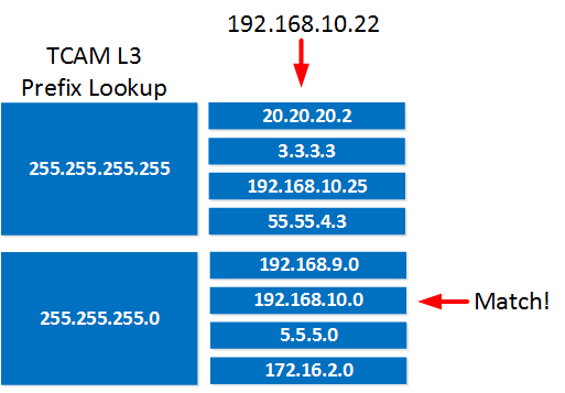
Whenever we need to match an IP packet against the routing table or an access-list we don’t always need an exact match. For example an IP packet with destination address 192.168.20.44 will match:
- 168.20.44 /32
- 168.20.0 /24
- 168.0.0 /16
Here’s an example of a TCAM table:
Now you know all the steps a multilayer switch has to take when it has to forward ip packets, the control/data plane and that we use different tables stored in special hardware called ASICs. Let’s take a closer look at the actual ‘forwarding’ of IP packets.
There are different switching methods to forward IP packets. Here are the different switching options:
- Process switching:
- All packets are examined by the CPU and all forwarding decisions are made in software…very slow!
- Fast switching (also known as route caching):
- The first packet in a flow is examined by the CPU; the forwarding decision is cached in hardware for the next packets in the same flow. This is a faster method.
- (CEF) Cisco Express Forwarding (also known as topology based switching):
- Forwarding table created in hardware beforehand. All packets will be switched using hardware. This is the fastest method but there are some limitations. Multilayer switches and routers use CEF.