Sunday, 10 January 2016

IPv6 Global unicast address

IPv6 Aggregatable global unicast address 


An aggregatable global address is an IPv6 address from the aggregatable global unicast prefix. The structure of aggregatable global unicast addresses enables strict aggregation of routing prefixes that limits the number of routing table entries in the global routing table. Aggregatable global addresses are used on links that are aggregated upward through organizations, and eventually to the Internet service providers (ISPs).
Aggregatable global IPv6 addresses are defined by a global routing prefix, a subnet ID, and an interface ID. Except for addresses that start with binary 000, all global unicast addresses have a 64-bit interface ID. The IPv6 global unicast address allocation uses the range of addresses that start with binary value 001 (2000::/3). The figure below shows the structure of an aggregatable global address.
Figure 1
Aggregatable Global Address Format


Addresses with a prefix of 2000::/3 (001) through E000::/3 (111) are required to have 64-bit interface identifiers in the extended universal identifier (EUI)-64 format. The Internet Assigned Numbers Authority (IANA) allocates the IPv6 address space in the range of 2000::/16 to regional registries.
The aggregatable global address typically consists of a 48-bit global routing prefix and a 16-bit subnet ID or Site-Level Aggregator (SLA). In the IPv6 aggregatable global unicast address format document (RFC 2374), the global routing prefix included two other hierarchically structured fields named Top-Level Aggregator (TLA) and Next-Level Aggregator (NLA). The IETF decided to remove the TLS and NLA fields from the RFCs because these fields are policy-based. Some existing IPv6 networks deployed before the change might still be using networks based on the older architecture.
A 16-bit subnet field called the subnet ID could be used by individual organizations to create their own local addressing hierarchy and to identify subnets. A subnet ID is similar to a subnet in IPv4, except that an organization with an IPv6 subnet ID can support up to 65,535 individual subnets.
An interface ID is used to identify interfaces on a link. The interface ID must be unique to the link. It may also be unique over a broader scope. In many cases, an interface ID will be the same as or based on the link-layer address of an interface. Interface IDs used in aggregatable global unicast and other IPv6 address types must be 64 bits long and constructed in the modified EUI-64 format.
Interface IDs are constructed in the modified EUI-64 format in one of the following ways:
  •  For all IEEE 802 interface types (for example, Ethernet, and FDDI interfaces), the first three octets (24 bits) are taken from the Organizationally Unique Identifier (OUI) of the 48-bit link-layer address (the Media Access Control [MAC] address) of the interface, the fourth and fifth octets (16 bits) are a fixed hexadecimal value of FFFE, and the last three octets (24 bits) are taken from the last three octets of the MAC address. The construction of the interface ID is completed by setting the Universal/Local (U/L) bit--the seventh bit of the first octet--to a value of 0 or 1. A value of 0 indicates a locally administered identifier; a value of 1 indicates a globally unique IPv6 interface identifier.
  •  For other interface types (for example, serial, loopback, ATM, Frame Relay, and tunnel interface types--except tunnel interfaces used with IPv6 overlay tunnels), the interface ID is constructed in the same way as the interface ID for IEEE 802 interface types; however, the first MAC address from the pool of MAC addresses in the router is used to construct the identifier (because the interface does not have a MAC address).
  •  For tunnel interface types that are used with IPv6 overlay tunnels, the interface ID is the IPv4 address assigned to the tunnel interface with all zeros in the high-order 32 bits of the identifier.

Note


For interfaces using Point-to-Point Protocol (PPP), given that the interfaces at both ends of the connection might have the same MAC address, the interface identifiers used at both ends of the connection are negotiated (picked randomly and, if necessary, reconstructed) until both identifiers are unique. The first MAC address in the router is used to construct the identifier for interfaces using PPP.

If no IEEE 802 interface types are in the router, link-local IPv6 addresses are generated on the interfaces in the router in the following sequence:
1.      The router is queried for MAC addresses (from the pool of MAC addresses in the router).
2.      If no MAC addresses are available in the router, the serial number of the router is used to form the link-local addresses.
3.      If the serial number of the router cannot be used to form the link-local addresses, the router uses a message digest algorithm 5 (MD5) hash to determine the MAC address of the router from the hostname of the router.


Understanding IPv6 Link local address


IPv6 Link local address 

The purpose of this document is to provide an understanding of IPv6 Link-local address in a network. 

A link-local address is an IPv6 unicast address that can be automatically configured on any interface using the link-local prefix FE80::/10 (1111 1110 10) and the interface identifier in the modified EUI-64 format. Link-local addresses are not necessarily bound to the MAC address (configured in a EUI-64 format). Link-local addresses can also be manually configured in the FE80::/10 format using the ipv6 address link-local command.

These addresses refer only to a particular physical link and are used for addressing on a single link for purposes such as automatic address configuration and neighbor discovery protocol. Link-local addresses can be used to reach the neighboring nodes attached to the same link. The nodes do not need a globally unique address to communicate. Routers will not forward datagram using link-local addresses. IPv6 routers must not forward packets that have link-local source or destination addresses to other links. All IPv6 enabled interfaces have a link-local unicast address.

So, In a computer network, a link-local address is a network address that is valid only for communications within the network segment (link) or the broadcast domain that the host is connected to.
Link-local addresses are usually not guaranteed to be unique beyond a single network segment. Routers therefore do not forward packets with link-local addresses.
For protocols that have only link-local addresses, such as Ethernet, hardware addresses that the manufacturer delivers in network circuits are unique, consisting of a vendor identification and a serial identifier.
Link-local addresses for IPv4 are defined in the address block 169.254.0.0/16, in CIDR notation. In IPv6, they are assigned with the FE80::/64 prefix. [1]

Video https://supportforums.cisco.com/video/11930026/understanding-ipv6-link-local-address 

In this example, the routers R1, R2 and R3 are connected via serial interface and have the IPv6 addresses configured as mentioned in the network diagram. Loopback addresses are configured on the routers R1 and R3, and the routers use OSPFv3 to communicate with each other. This example uses the ping command to demonstrate the connectivity between the routers using link-local addresses. The routers R1 and R3 can ping each other with the IPv6 global unicast address, but not with their link-local address. However, router R2 being directly connected to R1 and R3 can communicate with both the routers using their link-local address, because link-local addresses are used only within that local network specific to the physical interface.
t.
Network Diagram

ipv6-lla-01.gif


Router R1
!
hostname R1
!
ipv6 cef
!
ipv6 unicast-routing
!
interface Loopback10
 no ip address

 ipv6 address 2010::/64 eui-64

!--- Assigned a IPv6 unicast address in EUI-64 format.

  ipv6 ospf 1 area 1

!--- Enables OSPFv3 on the interface and associates
 the interface looback10 to area 1.

!
interface Loopback20
 no ip address

 ipv6 address 2020::/64 eui-64
 ipv6 ospf 1 area 2

!--- Associates the Interface loopback20 to area 2.

!
interface Serial0/0
 no ip address

 ipv6 address 2001::1/124
 ipv6 ospf 1 area 0

!--- Associates the Interface serial0/0 to area 0.

 clock rate 2000000
!
ipv6 router ospf 1
 router-id 1.1.1.1

!--- Router R1 uses 1.1.1.1 as router id.

 log-adjacency-changes
!
end

Router R2
Router R3
hostname R2
!
ipv6 cef
!
!
!
!
ipv6 unicast-routing
!
!
!
interface Serial0/0
 no ip address

 ipv6 address 2001::2/124
 ipv6 ospf 1 area 0
 clock rate 2000000
!
!
interface Serial0/1
 no ip address

 ipv6 address 2002::1/124
 ipv6 ospf 1 area 0
 clock rate 2000000
!
!
!
ipv6 router ospf 1
router-id 2.2.2.2
log-adjacency-changes
!
end
!
hostname R3
!
ipv6 cef
!
ipv6 unicast-routing
!
interface Loopback10
 no ip address

 ipv6 address 1010::/64 eui-64
 ipv6 ospf 1 area 1
!
interface Loopback20
 no ip address

 ipv6 address 2020::/64 eui-64
 ipv6 ospf 1 area 2
!
interface Serial0/0
 no ip address

 ipv6 address FE80::AB8 link-local
 ipv6 address 2002::2/124
 ipv6 ospf 1 area 0
 clock rate 2000000
!
ipv6 router ospf 1
 router-id 3.3.3.3
 log-adjacency-changes
!
end

Verifying OSPF Configuration

In order to verify the OSPF has been configured properly, use the show ipv6 route ospf command in routers R1 and R3.
show ipv6 route ospf
Router R1
R1#show ipv6 route ospf
IPv6 Routing Table - 10 entries
Codes: C - Connected, L - Local, S - Static, R - RIP, B - BGP
       U - Per-user Static route, M - MIPv6
       I1 - ISIS L1, I2 - ISIS L2, IA - ISIS interarea, IS - ISIS summary
       O - OSPF intra, OI - OSPF inter, OE1 - OSPF ext 1, OE2 - OSPF ext 2
       ON1 - OSPF NSSA ext 1, ON2 - OSPF NSSA ext 2
       D - EIGRP, EX - EIGRP external
OI  1010::C002:1DFF:FEE0:0/128 [110/128]
     via FE80::C001:1DFF:FEE0:0, Serial0/0
O   2002::/124 [110/128]
     via FE80::C001:1DFF:FEE0:0, Serial0/0
OI  2020::C002:1DFF:FEE0:0/128 [110/128]
     via FE80::C001:1DFF:FEE0:0, Serial0/0
Router R3
R3#show ipv6 route ospf
IPv6 Routing Table - 10 entries
Codes: C - Connected, L - Local, S - Static, R - RIP, B - BGP
       U - Per-user Static route, M - MIPv6
       I1 - ISIS L1, I2 - ISIS L2, IA - ISIS interarea, IS - ISIS summary
       O - OSPF intra, OI - OSPF inter, OE1 - OSPF ext 1, OE2 - OSPF ext 2
       ON1 - OSPF NSSA ext 1, ON2 - OSPF NSSA ext 2
       D - EIGRP, EX - EIGRP external
O   2001::/124 [110/128]
     via FE80::C001:1DFF:FEE0:0, Serial0/0
OI  2010::C000:1DFF:FEE0:0/128 [110/128]
     via FE80::C001:1DFF:FEE0:0, Serial0/0
OI  2020::C000:1DFF:FEE0:0/128 [110/128]
     via FE80::C001:1DFF:FEE0:0, Serial0/0

Verifying Link-Local Address Reachability

The routers can ping each other with the global unicast address. However, when using link-local address only the directly connected networks can communicate. For example, R1 can ping R3 using global unicast address but the two routers cannot communicate using link-local addresses. This is shown using the ping and debug ipv6 icmp commands in router R1 and R3. This section provides scenarios to develop a better understanding about link-local addresses.

Pinging Link-Local Address from Remote Network

When the router R1 tries to communicate with router R3 using the link local address, the router R1 returns with an ICMP time-out message indicating that the link-local address is locally specific and cannot communicate to link-local addresses that are outside the directly connected network.

Pinging R3's Link-Local Address from router R1
In Router R1
R1#ping FE80::AB8
 
!--- Pinging Link-Local Address of router R3.
 
Output Interface: serial0/0
 
!--- To ping LLA, output interface must be entered.
 
Type escape sequence to abort.
Sending 5, 100-byte ICMP Echos to FE80::AB8, timeout is 2 seconds:
Packet sent with a source address of FE80::C000:1DFF:FEE0:0
.....
Success rate is 0 percent (0/5)
 
!--- The ping is unsuccessful and the ICMP packet cannot reach
the destination through serial0/0. This timeout indicates that R1 has not
received any replies from the router R3.

For router R2, the routers R1 and R3 are directly connected and can ping the link-local address of both router R1 and R2 by mentioning the corresponding interface that is connected to the router. The output is shown here:

Pinging R1 Link-Local Addresses from router R2
In Router R2
R2#ping FE80::C000:1DFF:FEE0:0

!--- Pinging Link-Local Address of router R1.

Output Interface: serial0/0

!--- Note that, to ping LLA, output interface should be mentioned
In our case, R2 connects to R1 via serial0/0.

Type escape sequence to abort.
Sending 5, 100-byte ICMP Echos to FE80::C000:1DFF:FEE0:0, timeout is 2 seconds:
Packet sent with a source address of FE80::C001:1DFF:FEE0:0
!!!!!
Success rate is 100 percent (5/5), round-trip min/avg/max = 0/19/56 ms
Debug output from R1
R1#
*Mar  1 03:59:53.367: ICMPv6: Received echo request from FE80::C001:1DFF:FEE0:0
*Mar  1 03:59:53.371: ICMPv6: Sending echo reply to FE80::C001:1DFF:FEE0:0
*Mar  1 03:59:53.423: ICMPv6: Received echo request from FE80::C001:1DFF:FEE0:0
*Mar  1 03:59:53.427: ICMPv6: Sending echo reply to FE80::C001:1DFF:FEE0:0
*Mar  1 03:59:53.463: ICMPv6: Received echo request from FE80::C001:1DFF:FEE0:0
*Mar  1 03:59:53.463: ICMPv6: Sending echo reply to FE80::C001:1DFF:FEE0:0
*Mar  1 03:59:53.467: ICMPv6: Received echo request from FE80::C001:1DFF:FEE0:0
*Mar  1 03:59:53.467: ICMPv6: Sending echo reply to FE80::C001:1DFF:FEE0:0
R1#
*Mar  1 03:59:53.471: ICMPv6: Received echo request from FE80::C001:1DFF:FEE0:0
*Mar  1 03:59:53.471: ICMPv6: Sending echo reply to FE80::C001:1DFF:FEE0:0

!--- The debug output shows that the router R2 can
ping router R1's link-local address.

Pinging R3 Link-Local Addresses from router R2
In Router R2
R2#pingFE80::AB8

!--- Pinging Link-Local Address of router R3.

Output Interface: serial0/1

!--- Note that,to ping LLA,output interface should be mentioned.
In our case, R2 connects to R3 throught serial0/1.

Type escape sequence to abort.
Sending 5, 100-byte ICMP Echos to FE80::AB8, timeout is 2 seconds:
Packet sent with a source address of FE80::C001:1DFF:FEE0:0
!!!!!
Success rate is 100 percent (5/5), round-trip min/avg/max = 0/18/60 ms
Debug output from R3
R3#
*Mar  1 04:12:11.518: ICMPv6: Received echo request from FE80::C001:1DFF:FEE0:0
*Mar  1 04:12:11.522: ICMPv6: Sending echo reply to FE80::C001:1DFF:FEE0:0
*Mar  1 04:12:11.594: ICMPv6: Received echo request from FE80::C001:1DFF:FEE0:0
*Mar  1 04:12:11.598: ICMPv6: Sending echo reply to FE80::C001:1DFF:FEE0:0
*Mar  1 04:12:11.618: ICMPv6: Received echo request from FE80::C001:1DFF:FEE0:0
*Mar  1 04:12:11.618: ICMPv6: Sending echo reply to FE80::C001:1DFF:FEE0:0
*Mar  1 04:12:11.622: ICMPv6: Received echo request from FE80::C001:1DFF:FEE0:0
*Mar  1 04:12:11.622: ICMPv6: Sending echo reply to FE80::C001:1DFF:FEE0:0
R3#
*Mar  1 04:12:11.626: ICMPv6: Received echo request from FE80::C001:1DFF:FEE0:0
*Mar  1 04:12:11.630: ICMPv6: Sending echo reply to FE80::C001:1DFF:FEE0:0

!--- The debug output shows that the router R2 can
ping router R3's link-local address.
The link-local address as the name implies, is specific only to that local network. In other words, the routers can have the same link-local address and still the directly connected network can communicate with each other without any conflict. This will not be the same in case of global unicast address. The global unicast address being routable should be unique in a network. The show ipv6 interface brief command shows the information about link-local address on the interface.

show ipv6 interface brief
In router R1
R1#show ipv6 interface brief
Serial0/0                  [up/up]
    FE80::AB8
    2001::1
Loopback10                 [up/up]
    FE80::C000:1DFF:FEE0:0
    2010::C000:1DFF:FEE0:0
Loopback20                 [up/up]
    FE80::C000:1DFF:FEE0:0
    2020::C000:1DFF:FEE0:0
In router R3
R3#show ipv6 interface brief

Serial0/0                  [up/up]
    FE80::AB8
    2002::2
Loopback10                 [up/up]
    FE80::C002:1DFF:FEE0:0
    1010::C002:1DFF:FEE0:0
Loopback20                 [up/up]
    FE80::C002:1DFF:FEE0:0
    2020::C002:1DFF:FEE0:0

!--- Shows that R1 and R3's serial interface has same
link-local address FE80::AB8.
In this example, R1 and R3 are assigned with the same link-local address and R2 can still reach both the routers by specifying the corresponding output interface.

Pinging R1 and R3's Link-local address from R2
Pinging R1's link-local address from R2
R2#ping FE80::AB8
Output Interface: serial0/0

!--- R2 is connected to R1 through serial0/0.

Type escape sequence to abort.
Sending 5, 100-byte ICMP Echos to FE80::AB8, timeout is 2 seconds:
Packet sent with a source address of FE80::C001:1DFF:FEE0:0
!!!!!
Success rate is 100 percent (5/5), round-trip min/avg/max = 0/26/92 ms
Debug output from R1
R1#
*Mar  1 19:51:31.855: ICMPv6: Received echo request from FE80::C001:1DFF:FEE0:0
*Mar  1 19:51:31.859: ICMPv6: Sending echo reply to FE80::C001:1DFF:FEE0:0
*Mar  1 19:51:31.915: ICMPv6: Received echo request from FE80::C001:1DFF:FEE0:0
*Mar  1 19:51:31.919: ICMPv6: Sending echo reply to FE80::C001:1DFF:FEE0:0
*Mar  1 19:51:31.947: ICMPv6: Received echo request from FE80::C001:1DFF:FEE0:0
*Mar  1 19:51:31.947: ICMPv6: Sending echo reply to FE80::C001:1DFF:FEE0:0
*Mar  1 19:51:31.955: ICMPv6: Received echo request from FE80::C001:1DFF:FEE0:0
*Mar  1 19:51:31.955: ICMPv6: Sending echo reply to FE80::C001:1DFF:FEE0:0
R1#
*Mar  1 19:51:31.955: ICMPv6: Received echo request from FE80::C001:1DFF:FEE0:0
*Mar  1 19:51:31.955: ICMPv6: Sending echo reply to FE80::C001:1DFF:FEE0:0
Pinging R3's link-local address from R2
R2#ping FE80::AB8
Output Interface: serial0/1

!--- R2 is connected to R1 through serial0/1.

Type escape sequence to abort.
Sending 5, 100-byte ICMP Echos to FE80::AB8, timeout is 2 seconds:
Packet sent with a source address of FE80::C001:1DFF:FEE0:0
!!!!!
Success rate is 100 percent (5/5), round-trip min/avg/max = 4/28/76 ms
Debug output from R3
R3#
*Mar  1 19:53:38.815: ICMPv6: Received echo request from FE80::C001:1DFF:FEE0:0
*Mar  1 19:53:38.819: ICMPv6: Sending echo reply to FE80::C001:1DFF:FEE0:0
*Mar  1 19:53:38.911: ICMPv6: Received echo request from FE80::C001:1DFF:FEE0:0
*Mar  1 19:53:38.915: ICMPv6: Sending echo reply to FE80::C001:1DFF:FEE0:0
*Mar  1 19:53:38.923: ICMPv6: Received echo request from FE80::C001:1DFF:FEE0:0
*Mar  1 19:53:38.927: ICMPv6: Sending echo reply to FE80::C001:1DFF:FEE0:0
*Mar  1 19:53:38.955: ICMPv6: Received echo request from FE80::C001:1DFF:FEE0:0
*Mar  1 19:53:38.955: ICMPv6: Sending echo reply to FE80::C001:1DFF:FEE0:0
R3#
*Mar  1 19:53:38.963: ICMPv6: Received echo request from FE80::C001:1DFF:FEE0:0
*Mar  1 19:53:38.963: ICMPv6: Sending echo reply to FE80::C001:1DFF:FEE0:0

Note: The R2 can ping the link-local address of R1 and R3 only because they are directly connected. R2 cannot ping the link-local address of the loopback interfaces in routers R1 and R3 as they are not directly connected. Ping works on link-local addresses only in case of directly connected networks.
Note: Traceroutes do not work in case of link-local addresses and return with the % No valid source address for destination. error message. This is because IPv6 routers must not forward packets that have link-local source or destination addresses to other links.

IPv6 Quick Reference

This is a quick reference for IPv6

IPv6 Address Representation
Address space of IPv6 is 128 bits long. This mean that there is 2^128 of possible combinations that is roughly 3.4 * 10^38 logical unique addresses.
Typical representation is by using hexadecimal notation of X:X:X:X:X:X:X:X where X is case-insensitive 16bit field (mostly represented by 4x hexadecimal characters).
Example:
2031:0000:130f:0000:0000:09c0:876a:130b
There are ways to make this a bit shorter if there are sequences of “0000” in the address.
1) Leading zeroes in 16bit field are optional, so you can shorten “:09c0:” to “:9c0:”.
2) Group of 0 zeroes can be shorten to one zero like: “:0000:” -> “:0:”.
3) Continuos group or even whole fields of zeroes can be shorten like : “:0000:0000:” -> “::”. But only once inside an address!
Using this way of shortening address, the previous example can be shorten as this:
2031:0000:130f:0000:0000:09c0:876a:130b
is identical to
2031:0:130f::9c0:876a:130b

IPv6 Address Structure

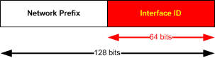
Unicast addresses are divided to two major field, first 64bits identify network, the second 64bits identify interface in IPv6 network. Note there will be no more “bits” borrowing and classical subnetting from IPv4 will change significantly.
IPv6_Unicast_address

NOTE: Interface ID can be also created dynamically in Ethernet network using MAC address (more info below).
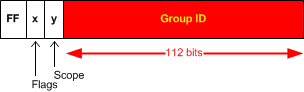
Multicast address identify a set of interfaces, to identify a multicast address, first 8 bits are all ones or “FF”. All multicast IPv6 addresses start as “FF……”. Followed by 4bit “flag field” and 4 bit “scope field” and a 112bit “group ID”.
IPv6_Multicast_address
4bit Flag field:
“0” -> reserved and must be 0
R -> Indicates randezvous point and is almost always set to 0
P -> Indicates prefix dependency and is almost always set to 0
T -> Temporary bit. For a temporary unicast address set to 1.
NOTE: if R is 1, then P and T is also set to 1.
4bit Scope field:
Depending on the value of the 4 bits
1 = Interface Local
2 = Link Local
3 = Subnet Local
4 = Admin Local
5 = Site Local
8 = Organization
E = Global
NOTE: There is no TTL field in IPv6 multicast. So scoping is defined inside the address
Example: FF02::/16 is Multicast permanent address with Link-Local scope.

Types of IPv6 Unicast Addresses

Link-Local IPv6 Unicast Address is basic type of IPv6 and every IPv6 enabled interface must generate itself automatically this address. To generate link local address, interface takes link-local reserved prefix fe80::/10 and a 64bit interface ID.
When communicating with Link-Local IPv6 addresses, you have to specify outgoing interface as the same subnet is essentially on all these interfaces.
Global IPv6 Unicast Address is for principal use of IP addressing. The structure is as follows:
  • Global routing prefix, typically /48 that is assigned by ISP
  • A subnet ID, typically 16 bits that identify links inside a site
  • Interface ID that is 64 bits
Local IPv6 Unicast Addresses are designed as a replacement for a site-local addresses, specifically to resolve scoping issues. These addresses use reserved FD00::/8 prefix, followed by 40 bits of random identifier (generated by SHA-1 with input of 64bit time + universal EUI-64 identifier), then administrator is free to do local subnetting in 16 bits and last 64bit is typical Interface ID.

IPv6_lical IPv6 unicast
Anycast IPv6 Addresses are used in “one-to-many” or better “one-to-nearest” needs. When a packet is sent to this
address, it is routed to the nearest interface that has this address. The nearest is found by using metrics in routing protocols.
The Anycast addresses are allocated from global IPv6 pool and are undistinguished from normal unicast addresses. Node using anycast address must be explicitly configured to know this is an anycast address.
NOTE: In today IPv4 Internet, this function is currently done by DNS servers that resolved hostnames with the nearest IPv4 unicast address as a form one-to-nearest system for hosting wold-wide services. So IPv6 anycast is underused today.

Special purpose IPv6 Unicast Addresses

Unspecified address:
0:0:0:0:0:0:0:0 – used until DHCP or until IPv6 is generated automatically
Loopback IPv6 Address:
0:0:0:0:0:0:0:1 – same as 127:0:0:1
IPv4 mapped addresses:
Used to represent IPv4 address nodes as IPv6 addresses
Used for next-hop representation in Cisco 6PE and 6VPE
Used in network stack when both address families are processed internally as IPv6
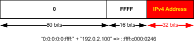
To generate IPv4 to IPv6 mapped address, simply add 0:0:0:0:0:FFFF: in front of the IPv4 32 bits as follows:
IPv4toIPv6Mapping

IPv6 Header

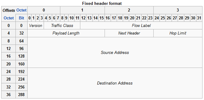
IPv6 header is 40 Bytes (octets) long. This is its structure:
IPv6_Header
Version – 4 bit that contains the number 6 instead of 4 in IPv4.
Traffic Class – This 8 bit field is like Type of Service field in IPv4. So preferential treatment can be mapped to a packed by marking in this field.
Flow label – this 20bit field can be used to mark each flow (for example one TCP session or UDP stream) to give per-flow non-default treatment to it if needed.
Payload Length – This 16 bit field is like “Total Length” in IPv4, but in IPv6 this describes the length of payload only (IPv4 Total Length counted IPv4 header length to the number).
Next Header – Determines the header/information following the IPv6 header. It can be either another encapsulated protocol like TCP/UDP, or IPv6 extension header.
Hop Limit – 8 bit field that acts similarrly like TTL in IPv4.
Source Address – 128 bits of source IPv6 address
Destination Address – 128 bits of destination IPv6 address

IPv6 Address Asssigment

Static Interface ID can be assigned manually or automatically generated from MAC address using EUI-64.
Dynamic Interface ID can be assigned by DHCPv6 (statefully) or stateless* be negotiating with the nearest IPv6 router.
* In stateless configuration the host sends “Router Solicitation” message on Link-Local subnet requesting prefix information from nearby router on that segment. The router responds sending the host prefix/default gateway/DNS information. Host combines received prefix with his autogenerated Interface ID to create his global unicast IPv6 address.

ICMPv6

The ICMPv6 has a few changes that needs to be mentioned in comparison to the ICMPv4 (in IPv4).
First, the codes used to identify type of message have changed. Quick overview table:
ICMP types:
  • Destination Unreachable – IPv4: 3 – IPv6: 1
  • Packet Too Big – IPv4: NONE – IPv6: 2
  • Fragmentation Needed – IPv4: 3 – IPv6: NONE
  • Time Exceeded – IPv4: 11 – IPv6: 3
  • Parameter Problem – IPv4: 12 – IPv6: 4
  • Echo Request – IPv4: 8 – IPv6: 128
  • Echo Reply – IPv4: 0 – IPv6: 129
An ICMP type 2 (in IPv6 only) error message is an integral piece of discovering the maximum MTU of the path to the destination. Unlike the IPv4 version that only reported the reason of packet drop is MTU, in ICMPv6 the can carry exactly the next-link MTU so that the source can quickly adjust.

ICMP and IPv6 Neighbor Discovery

ICMP in IPv6 also takes several additional functions using IPv6 link-local multicast
  • Determines the layer 2 address of a neighbor on the same link (just like ARP does in IPv4).
  • Dynamically finds neighbor routers
  • Keeps track of neighbors
ICMPv6 type 133 – Router Solicitation
A node sends its address in the early stage of the boot process. Instead of waiting for the next router advertisement to get the information. This message essentially asks all routers on the link to reply immediately with Router Advertisement (instead of waiting for their periodic Router Advertisements).
ICMPv6 type 134 – Router Advertisement
Router Advertisements are send periodically or as a reply to Router Solicitation messages.
ICMPv6 type 135 – Neighbor Solicitation
Neighbor solicitation is a process of determining the data link layer address of a neighbor. This is the same function as ARP does, but uses link-local multicast ICMPv6.
ICMPv6 type 136 – Neighbor Advertisement
neighbor advertisement works with neighbor solicitation to do layer 2 address resolution function (instead of ARP in IPv4). Neighbor Advertisement is either sent graciously after self configuration or as a reply to Neighbor Solicitation message and holds layer 2 data link address of the source node.
 ICMPv6 type 137 – Redirect Message
A router gives Redirect Message to signal the rerouting of a packet to a better on-link router. The receiving node reroutes all subsequent packets to the target router.