Sunday, 10 January 2016

IPv6 Quick Reference

This is a quick reference for IPv6

IPv6 Address Representation
Address space of IPv6 is 128 bits long. This mean that there is 2^128 of possible combinations that is roughly 3.4 * 10^38 logical unique addresses.
Typical representation is by using hexadecimal notation of X:X:X:X:X:X:X:X where X is case-insensitive 16bit field (mostly represented by 4x hexadecimal characters).
Example:
2031:0000:130f:0000:0000:09c0:876a:130b
There are ways to make this a bit shorter if there are sequences of “0000” in the address.
1) Leading zeroes in 16bit field are optional, so you can shorten “:09c0:” to “:9c0:”.
2) Group of 0 zeroes can be shorten to one zero like: “:0000:” -> “:0:”.
3) Continuos group or even whole fields of zeroes can be shorten like : “:0000:0000:” -> “::”. But only once inside an address!
Using this way of shortening address, the previous example can be shorten as this:
2031:0000:130f:0000:0000:09c0:876a:130b
is identical to
2031:0:130f::9c0:876a:130b

IPv6 Address Structure

Unicast addresses are divided to two major field, first 64bits identify network, the second 64bits identify interface in IPv6 network. Note there will be no more “bits” borrowing and classical subnetting from IPv4 will change significantly.
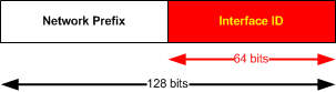
IPv6_Unicast_address

NOTE: Interface ID can be also created dynamically in Ethernet network using MAC address (more info below).
Multicast address identify a set of interfaces, to identify a multicast address, first 8 bits are all ones or “FF”. All multicast IPv6 addresses start as “FF……”. Followed by 4bit “flag field” and 4 bit “scope field” and a 112bit “group ID”.
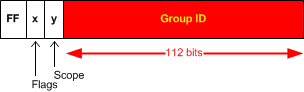
IPv6_Multicast_address
4bit Flag field:
“0” -> reserved and must be 0
R -> Indicates randezvous point and is almost always set to 0
P -> Indicates prefix dependency and is almost always set to 0
T -> Temporary bit. For a temporary unicast address set to 1.
NOTE: if R is 1, then P and T is also set to 1.
4bit Scope field:
Depending on the value of the 4 bits
1 = Interface Local
2 = Link Local
3 = Subnet Local
4 = Admin Local
5 = Site Local
8 = Organization
E = Global
NOTE: There is no TTL field in IPv6 multicast. So scoping is defined inside the address
Example: FF02::/16 is Multicast permanent address with Link-Local scope.

Types of IPv6 Unicast Addresses

Link-Local IPv6 Unicast Address is basic type of IPv6 and every IPv6 enabled interface must generate itself automatically this address. To generate link local address, interface takes link-local reserved prefix fe80::/10 and a 64bit interface ID.
When communicating with Link-Local IPv6 addresses, you have to specify outgoing interface as the same subnet is essentially on all these interfaces.
Global IPv6 Unicast Address is for principal use of IP addressing. The structure is as follows:
  • Global routing prefix, typically /48 that is assigned by ISP
  • A subnet ID, typically 16 bits that identify links inside a site
  • Interface ID that is 64 bits
Local IPv6 Unicast Addresses are designed as a replacement for a site-local addresses, specifically to resolve scoping issues. These addresses use reserved FD00::/8 prefix, followed by 40 bits of random identifier (generated by SHA-1 with input of 64bit time + universal EUI-64 identifier), then administrator is free to do local subnetting in 16 bits and last 64bit is typical Interface ID.

IPv6_lical IPv6 unicast
Anycast IPv6 Addresses are used in “one-to-many” or better “one-to-nearest” needs. When a packet is sent to this
address, it is routed to the nearest interface that has this address. The nearest is found by using metrics in routing protocols.
The Anycast addresses are allocated from global IPv6 pool and are undistinguished from normal unicast addresses. Node using anycast address must be explicitly configured to know this is an anycast address.
NOTE: In today IPv4 Internet, this function is currently done by DNS servers that resolved hostnames with the nearest IPv4 unicast address as a form one-to-nearest system for hosting wold-wide services. So IPv6 anycast is underused today.

Special purpose IPv6 Unicast Addresses

Unspecified address:
0:0:0:0:0:0:0:0 – used until DHCP or until IPv6 is generated automatically
Loopback IPv6 Address:
0:0:0:0:0:0:0:1 – same as 127:0:0:1
IPv4 mapped addresses:
Used to represent IPv4 address nodes as IPv6 addresses
Used for next-hop representation in Cisco 6PE and 6VPE
Used in network stack when both address families are processed internally as IPv6
To generate IPv4 to IPv6 mapped address, simply add 0:0:0:0:0:FFFF: in front of the IPv4 32 bits as follows:
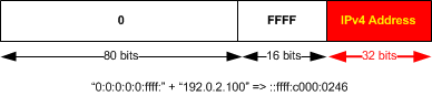
IPv4toIPv6Mapping

IPv6 Header

IPv6 header is 40 Bytes (octets) long. This is its structure:
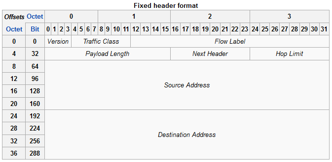
IPv6_Header
Version – 4 bit that contains the number 6 instead of 4 in IPv4.
Traffic Class – This 8 bit field is like Type of Service field in IPv4. So preferential treatment can be mapped to a packed by marking in this field.
Flow label – this 20bit field can be used to mark each flow (for example one TCP session or UDP stream) to give per-flow non-default treatment to it if needed.
Payload Length – This 16 bit field is like “Total Length” in IPv4, but in IPv6 this describes the length of payload only (IPv4 Total Length counted IPv4 header length to the number).
Next Header – Determines the header/information following the IPv6 header. It can be either another encapsulated protocol like TCP/UDP, or IPv6 extension header.
Hop Limit – 8 bit field that acts similarrly like TTL in IPv4.
Source Address – 128 bits of source IPv6 address
Destination Address – 128 bits of destination IPv6 address

IPv6 Address Asssigment

Static Interface ID can be assigned manually or automatically generated from MAC address using EUI-64.
Dynamic Interface ID can be assigned by DHCPv6 (statefully) or stateless* be negotiating with the nearest IPv6 router.
* In stateless configuration the host sends “Router Solicitation” message on Link-Local subnet requesting prefix information from nearby router on that segment. The router responds sending the host prefix/default gateway/DNS information. Host combines received prefix with his autogenerated Interface ID to create his global unicast IPv6 address.

ICMPv6

The ICMPv6 has a few changes that needs to be mentioned in comparison to the ICMPv4 (in IPv4).
First, the codes used to identify type of message have changed. Quick overview table:
ICMP types:
  • Destination Unreachable – IPv4: 3 – IPv6: 1
  • Packet Too Big – IPv4: NONE – IPv6: 2
  • Fragmentation Needed – IPv4: 3 – IPv6: NONE
  • Time Exceeded – IPv4: 11 – IPv6: 3
  • Parameter Problem – IPv4: 12 – IPv6: 4
  • Echo Request – IPv4: 8 – IPv6: 128
  • Echo Reply – IPv4: 0 – IPv6: 129
An ICMP type 2 (in IPv6 only) error message is an integral piece of discovering the maximum MTU of the path to the destination. Unlike the IPv4 version that only reported the reason of packet drop is MTU, in ICMPv6 the can carry exactly the next-link MTU so that the source can quickly adjust.

ICMP and IPv6 Neighbor Discovery

ICMP in IPv6 also takes several additional functions using IPv6 link-local multicast
  • Determines the layer 2 address of a neighbor on the same link (just like ARP does in IPv4).
  • Dynamically finds neighbor routers
  • Keeps track of neighbors
ICMPv6 type 133 – Router Solicitation
A node sends its address in the early stage of the boot process. Instead of waiting for the next router advertisement to get the information. This message essentially asks all routers on the link to reply immediately with Router Advertisement (instead of waiting for their periodic Router Advertisements).
ICMPv6 type 134 – Router Advertisement
Router Advertisements are send periodically or as a reply to Router Solicitation messages.
ICMPv6 type 135 – Neighbor Solicitation
Neighbor solicitation is a process of determining the data link layer address of a neighbor. This is the same function as ARP does, but uses link-local multicast ICMPv6.
ICMPv6 type 136 – Neighbor Advertisement
neighbor advertisement works with neighbor solicitation to do layer 2 address resolution function (instead of ARP in IPv4). Neighbor Advertisement is either sent graciously after self configuration or as a reply to Neighbor Solicitation message and holds layer 2 data link address of the source node.
 ICMPv6 type 137 – Redirect Message
A router gives Redirect Message to signal the rerouting of a packet to a better on-link router. The receiving node reroutes all subsequent packets to the target router.

Friday, 13 November 2015

EIGRP offset-list in name mode

Same topology like before in EIGRP-offset-list classic mode , we are increasing the metric to reach
lo0 in R2


R1#
R1#sh ip access-list
Standard IP access list 2
    10 permit 2.2.2.2
R1#
R1#sh run | s router
router eigrp cisco6
router eigrp cisco
 !
 address-family ipv4 unicast autonomous-system 100
  !
  topology base _+++++++++++++++note we have to conig everything in topology base
   redistribute connected metric 10000 1 255 1 1500 route-map CONN
   offset-list 2 in 300 Serial2/0
   offset-list 2 in 300 Serial2/2
  exit-af-topology
  network 192.168.12.0
  network 192.168.21.0
 exit-address-family


This is before we applied the offset-list

R1(config-router-af)#do sh ip eigrp topo
EIGRP-IPv4 VR(cisco) Topology Table for AS(100)/ID(10.10.60.1)
Codes: P - Passive, A - Active, U - Update, Q - Query, R - Reply,
       r - reply Status, s - sia Status

P 192.168.23.0/24, 2 successors, FD is 3045896258
        via 192.168.12.2 (3045896258/1735176258), Serial2/0
        via 192.168.21.1 (3045896258/1735176258), Serial2/2
P 192.168.21.0/24, 1 successors, FD is 1735175958
        via Connected, Serial2/2
P 10.10.110.0/24, 2 successors, FD is 3374344258
        via 192.168.12.2 (3374344258/2063624258), Serial2/0
        via 192.168.21.1 (3374344258/2063624258), Serial2/2
P 192.168.12.0/24, 1 successors, FD is 1735175958
        via Connected, Serial2/0
P 10.10.30.0/24, 1 successors, FD is 66191360
        via Rconnected (66191360/0)
P 10.10.140.0/24, 2 successors, FD is 3374344258
        via 192.168.12.2 (3374344258/2063624258), Serial2/0
        via 192.168.21.1 (3374344258/2063624258), Serial2/2
P 10.10.150.0/24, 2 successors, FD is 3374344258
        via 192.168.12.2 (3374344258/2063624258), Serial2/0
        via 192.168.21.1 (3374344258/2063624258), Serial2/2
P 2.2.2.0/24, 2 successors, FD is 2062856258 <+++++++before after  2062855958
        via 192.168.12.2 (2062856258/327762220), Serial2/0
        via 192.168.21.1 (2062856258/327762220), Serial2/2
P 10.10.60.0/24, 1 successors, FD is 66191360, tag is 60
        via Rconnected (66191360/0)
P 192.168.32.0/24, 2 successors, FD is 3901440300
        via 192.168.12.2 (3901440300/2590720300), Serial2/0
        via 192.168.21.1 (3901440300/2590720300), Serial2/2
P 10.10.20.0/24, 1 successors, FD is 66191360
        via Rconnected (66191360/0)
P 10.10.40.0/24, 1 successors, FD is 66191360
        via Rconnected (66191360/0)
P 10.10.130.0/24, 2 successors, FD is 3374344258
        via 192.168.12.2 (3374344258/2063624258), Serial2/0
        via 192.168.21.1 (3374344258/2063624258), Serial2/2
P 3.3.3.3/32, 2 successors, FD is 3374344258
        via 192.168.12.2 (3374344258/2063624258), Serial2/0
        via 192.168.21.1 (3374344258/2063624258), Serial2/2
P 10.1.1.0/30, 1 successors, FD is 66191360
        via Rconnected (66191360/0)
P 10.10.10.0/24, 1 successors, FD is 66191360
        via Rconnected (66191360/0)
P 1.1.1.1/32, 1 successors, FD is 66191360
        via Rconnected (66191360/0)
P 10.10.50.0/24, 1 successors, FD is 66191360
        via Rconnected (66191360/0)
P 10.10.120.0/24, 2 successors, FD is 3374344258
        via 192.168.12.2 (3374344258/2063624258), Serial2/0
        via 192.168.21.1 (3374344258/2063624258), Serial2/2

R1(config-std-nacl)#permit host 2.2.2.2R1(config-std-nacl)#exit
R1(config)#d sh ip eigrp topo
*Nov 13 17:38:54.956: %DUAL-5-NBRCHANGE: EIGRP-IPv4 100: Neighbor 192.168.12.2 (Serial2/0) is resync: intf route configuration changed
*Nov 13 17:38:54.956: %DUAL-5-NBRCHANGE: EIGRP-IPv4 100: Neighbor 192.168.21.1 (Serial2/2) is resync: intf route configuration changed

R1(config)#do sh ip eigrp topo | b 2.2.2.0
P 2.2.2.0/24, 2 successors, FD is 2062855958 +++++++++++++300 ADDED
        via 192.168.12.2 (2062855958/327761920), Serial2/0
        via 192.168.21.1 (2062855958/327761920), Serial2/2
P 10.10.60.0/24, 1 successors, FD is 66191360, tag is 60
        via Rconnected (66191360/0)
P 192.168.32.0/24, 2 successors, FD is 3901440000
        via 192.168.12.2 (3901440000/2590720000), Serial2/0
        via 192.168.21.1 (3901440000/2590720000), Serial2/2
P 10.10.20.0/24, 1 successors, FD is 66191360
        via Rconnected (66191360/0)
P 10.10.40.0/24, 1 successors, FD is 66191360
        via Rconnected (66191360/0)
P 10.10.130.0/24, 2 successors, FD is 3374343958
        via 192.168.12.2 (3374343958/2063623958), Serial2/0
        via 192.168.21.1 (3374343958/2063623958), Serial2/2
P 3.3.3.3/32, 2 successors, FD is 3374343958
        via 192.168.12.2 (3374343958/2063623958), Serial2/0
        via 192.168.21.1 (3374343958/2063623958), Serial2/2
P 10.1.1.0/30, 1 successors, FD is 66191360
        via Rconnected (66191360/0)
P 10.10.10.0/24, 1 successors, FD is 66191360
        via Rconnected (66191360/0)
P 1.1.1.1/32, 1 successors, FD is 66191360

R1(config)#sh run

EIGRP offset-list


This another method to influence the metric in a routing protocol. The offset-list lets you increase the metric when you send a routing update to your neighbor or when you receive it.
You can use this for RIP or EIGRP, it is not supported for OSPF.

In this example wewill show how we can increase the metric


 lo01.1.1.1      lo02.2.2.2
R1 ========R2===========R3 (loopback 3.3.3.3)


R2#sh ip eigrp topo
P 10.10.130.0/24, 1 successors, FD is 2297856
        via 192.168.23.3 (2297856/128256), Serial2/1
        via 192.168.32.3 (5639936/128256), Ethernet0/1
P 3.3.3.3/32, 1 successors, FD is 2297856 ++++++++++++++
        via 192.168.23.3 (2297856/128256), Serial2/1
        via 192.168.32.3 (5639936/128256), Ethernet0/1
P 10.1.1.0/30, 2 successors, FD is 2195456
        via 192.168.12.1 (2195456/281600), Serial2/0
        via 192.168.21.2 (2195456/281600), Serial2/2
P 10.10.10.0/24, 2 successors, FD is 2297856
        via 192.168.12.1 (2297856/128256), Serial2/0
        via 192.168.21.2 (2297856/128256), Serial2/2


We introduce in router R2 a offset-list to reach 3.3.3.3


R2(config)#ip access-list standard 2
R2(config-std-nacl)#permit host 3.3.3.3

R2(config-std-nacl)#
R2(config-std-nacl)#end
R2#

R2(config)#router eigrp 100
R2(config-router)#off
R2(config-router)#offset-list 1 ?
  in   Perform offset on incoming updates
  out  Perform offset on outgoing updates

R2(config-router)#offset-list 1 in 300 se2/1
R2(config-router)#offset-list 1 out 300 se2/1

after
R2(config-router)#do sh ip eigrp topology | b 3.3.3.3
P 3.3.3.3/32, 1 successors, FD is 2298156 _++++++++++++++++++++
        via 192.168.23.3 (2298156/128512), Serial2/1
        via 192.168.32.3 (5639936/128256), Ethernet0/1
P 10.1.1.0/30, 2 successors, FD is 2195456
        via 192.168.12.1 (2195456/281600), Serial2/0
        via 192.168.21.2 (2195456/281600), Serial2/2
P 10.10.10.0/24, 2 successors, FD is 2297856
        via 192.168.12.1 (2297856/128256), Serial2/0
        via 192.168.21.2 (2297856/128256), Serial2/2
P 1.1.1.1/32, 2 successors, FD is 2170112
        via 192.168.12.1 (2170112/256256), Serial2/0
        via 192.168.21.2 (2170112/256256), Serial2/2
P 10.10.50.0/24, 2 successors, FD is 2297856
        via 192.168.12.1 (2297856/128256), Serial2/0
        via 192.168.21.2 (2297856/128256), Serial2/2
P 10.10.120.0/24, 1 successors, FD is 2298156
        via 192.168.23.3 (2298156/128512), Serial2/1
        via 192.168.32.3 (5639936/128256), Ethernet0/1

R2(config-router)#

Wednesday, 4 November 2015

EGRP name mode

This gives you glimpse of EIGRP name mode configuration.

In traditional way we were configuring EIGRP like this,

We go to configuration mode and defining EIGRP with process number

R1#conf t
R1(config)#router eigrp 1
R1(config-router)#

After that if we have to run EIGRP on the interfaces then we have to specify each network with wildcard mask for every interface:

R1(config-router)#network 10.1.1.0 0.0.0.3
R1(config-router)#network 1.1.1.1 0.0.0.0


And for some the command like EIGRP authentication, defining Bandwidth to control EIGRP packets or to define EIGRP next-hop you have exit Router config mode and switch to interface mode as shown below:

R1(config-router)#exit
R1(config)#int fa0/0
R1(config-if)#ip authentication mode eigrp 1 md5
R1(config-if)#ip authentication key-chain eigrp 1 cisco
R1(config-if)#ip bandwidth-percent eigrp 1 75

This was what we discussed for IPv4 Eigrp. Now to run EIGRP for IPv6 we have to configure in different way define the IPv6 router process and run Eigrp under interface mode.

ipv6 router eigrp 1
eigrp router-id 10.1.1.1
no shut
!
Interface f0/0
ipv6 enabe
ipv6 eigrp 1
!

So In traditional way for every address family (IPv4/VRF/IPv6) you have to configure EIGRP separately .You have to switch config mode to interface mode, also another interesting point is that there was no way to configure VRF in traditional IPv6 EIGRP implementation but in “EIGRP Name Mode configuration” you can config all in one place, plus you have the option to run IPv6 Eigrp for VRF

Let’s discussed EIGRP name mode configuration in detail.

EIGRP named configuration is available in following IOS release and onwards:

15.0(1)M

12.2(33)SRE

12.2(33)XNE

Cisco IOS XE Release 2.5

If you are running any of the above IOS versions then you will see 2 options after you do question mark as shown. 

R2(config)#router eigrp ?
  <1-65535> Autonomous System
  WORD       EIGRP Virtual-Instance Name

To define Name mode configuration define word option as show below:

R2(config)#router eigrp CISCO

Unlike traditional way, EIGRP instance not create or it doesn't start running the moment following is configured on the router. The instance will be created when address-family and autonomous system number is configured for e.g.:


For IPv4:

R2(config-router)#address-family ipv4 unicast autonomous-system 1

For IPv4 VRF:

R2(config-router)#address-family ipv4 unicast vrf Customer_A autonomous-system 1

For IPv6:

R2(config-router)#address-family ipv6 unicast autonomous-system 1

For IPv6 VRF

R2(config-router)#address-family ipv6 unicast vrf site_A autonomous-system 1

With this Named mode, we can create a single Instance of EIGRP, which can be used for all address family type as shown above.
Another simplicity is if want to turn off the entire AS, you can use “shutdown” command under address-family to turn off the entire instance.


Named EIGRP has 3 configuration modes. These are:

    1) address-family configuration mode - (config-router-af)#
    2) address-family interface configuration mode - (config-router-af-interface)#
    3) address-family topology configuration mode - (config-router-af-topology)#

A) Address-family configuration mode:

In this mode, you can configure networks, EIGRP neighbor, EIGRP Router-id, metric etc. From this mode you can access the other two configuration modes used in EIGRP named configuration.

R2(config-router)#address-family ipv4 unicast autonomous-system 1
R2(config-router-af)#?
Address Family configuration commands:
  af-interface         Enter Address Family interface configuration
  default              Set a command to its defaults
  eigrp                EIGRP Address Family specific commands
  exit-address-family  Exit Address Family configuration mode
  help                 Description of the interactive help system
  maximum-prefix       Maximum number of prefixes acceptable in aggregate
  metric               Modify metrics and parameters for address advertisement
  neighbor             Specify an IPv4 neighbor router
  network              Enable routing on an IP network
  no                   Negate a command or set its defaults
  shutdown             Shutdown address family
  timers               Adjust peering based timers
  topology             Topology configuration mode

R2(config-router-af)#

B) Address-family interface configuration mode:

This mode takes all the interface specific commands that were previously configured on an actual interface (logical or physical) and moves them into the EIGRP configuration. EIGRP authentication, Bandwidth-percentage, split-horizon, and summary-address configuration are some of the options that are now configured here instead of in interface configuration mode.

R2(config-router-af)#af-interface fa0/0
R2(config-router-af-interface)#?
Address Family Interfaces configuration commands:
  authentication      authentication subcommands
  bandwidth-percent   Set percentage of bandwidth percentage limit
  bfd                 Enable Bidirectional Forwarding Detection
  dampening-change    Percent interface metric must change to cause update
  dampening-interval  Time in seconds to check interface metrics
  default             Set a command to its defaults
  exit-af-interface   Exit from Address Family Interface configuration mode
  hello-interval      Configures hello interval
  hold-time           Configures hold time
  next-hop-self       Configures EIGRP next-hop-self
  no                  Negate a command or set its defaults
  passive-interface   Suppress address updates on an interface
  shutdown            Disable Address-Family on interface
  split-horizon       Perform split horizon
  summary-address     Perform address summarization

R2(config-router-af-interface)#

In traditional way if we want run EIGRP on all interface we use "network 0.0.0.0 0.0.0.0" command. Here you can use “af-interface default” to function same.

R2(config-router-af)#af-interface default
R2(config-router-af-interface)#

C) Address-family topology configuration mode:

This mode provide several options which operates on EIGRP topology table .here you can define content like redistribution, distance, offset list, variance etc. To enter this mode, we need to go back to address-family configuration mode:

R2(config-router-af-interface)#exit
R2(config-router-af)#topology base
R2(config-router-af-topology)#?
Address Family Topology configuration commands:
  auto-summary         Enable automatic network number summarization
  default              Set a command to its defaults
  default-information  Control distribution of default information
  default-metric       Set metric of redistributed routes
  distance             Define an administrative distance
  distribute-list      Filter entries in eigrp updates
  eigrp                EIGRP specific commands
  exit-af-topology     Exit from Address Family Topology configuration mode
  fast-reroute         Configure Fast-Reroute
  maximum-paths        Forward packets over multiple paths
  metric               Modify metrics and parameters for advertisement
  no                   Negate a command or set its defaults
  offset-list          Add or subtract offset from EIGRP metrics
  redistribute         Redistribute IPv4 routes from another routing protocol
  snmp                 Modify snmp parameters
  summary-metric       Specify summary to apply metric/filtering
  timers               Adjust topology specific timers
  traffic-share        How to compute traffic share over alternate paths
  variance             Control load balancing variance

R2(config-router-af-topology)#

Comparison chart between Eigrp “traditional Configuration” and “Name mode Configuration”:

EIGRP Tradition way of ConfigurationEIGRP Name Mode Configuration
int fa0/0
ip add 10.1.1.1 255.255.255.252
ip authentication mode eigrp 1 md5
ip authentication key-chain eigrp 1 cisco
ip bandwidth-percent eigrp 1 75 
ip hello eigrp 1 10
IPv6 enable
IPv6 eigrp 1


router eigrp 1
network 10.1.1.0 0.0.0.3
redistribute connected


ipv6 router eigrp 1
eigrp router-id 10.1.1.1
no shut


router eigrp 2
address-family ipv4 vrf CUST_A
network 0.0.0.0 0.0.0.0


"No IPv6 EIGRP support for VRF"
int fa0/0
ip add 10.1.1.1 255.255.255.252
IPv6 enable


router eigrp CISCO
!
address-family ipv6 unicast autonomous-system 1
  !
  topology base
  exit-af-topology
  eigrp router-id 1.1.1.1
exit-address-family
!
address-family ipv4 unicast autonomous-system 1
  !
  af-interface FastEthernet0/0
   authentication mode md5
   authentication key-chain cisco
   bandwidth-percent 75
   hello-interval 10
  exit-af-interface
  !
  topology base
   redistribute connected
  exit-af-topology
exit-address-family
!
address-family ipv6 unicast vrf CUST_B autonomous-system 2
  !
  topology base
  exit-af-topology
exit-address-family
!
address-family ipv4 unicast vrf CUST_A autonomous-system 2
  !
af-interface default
!
  topology base
  exit-af-topology
exit-address-family