Monday, 19 October 2015

1.1d(iii) IPv4 and IPv6 fragmentation

IPv4 and IPv6 fragmentation

IPv4 Fragmentation-

When an IPv4 packet is larger than the network's MTU(default to 1500), and the DF bit within the IP header is clear the packet will be fragmented into smaller pieces so it can be sent to the other end. The maximum size of each piece is the MTU minus the IP header size (20 bytes minimum; 60 bytes maximum).

Fragmentation has a negative impact on router's performance and it should be avoided when possible.

IPv6 Fragmentation-

As opposed to IPv4, fragmentation in IPv6 is performed by the IPv6 enabled nodes not by the routers along the path. If an intermediate node such as a router receives an IPv6 packet that needs to be fragmented, it will discard the packet and send an ICMPv6 Packet Too Big error message back to the source as routers will not attempt to perform fragmentation unless they are the source of the IPv6 packet.

1.1d(ii) IPV4 options, IPv6 Extension Headers

IPv4 Options

IPv4 Options

Below a visual description of the Header options found within an IPv4 packet:

IP Header

Here is a description of every option field within the IP header:

Version: Version number of Internet Protocol used. For IPv6 Packet this field will be set to 6.

IHL: Internet Header Length(4 bits field), this value tells how big the packet is. The minimum value allowed is 5 which would be 20 bytes (no options). The maximum value possible is 15, for a packet header length of 60 bytes (allowing a maximum of 40 bytes for "options").

DSCP: Differentiated Services Code Point, this is where you can apply your QoS tags.

ECN: Explicit Congestion Notification, carries information about the congestion seen in the route.

Total Length: Length of entire IP Packet (including IP header and IP Payload). This field (16 bits) contains the total length of the packet, including the packet header, in bytes. The minimum length is 20 (20 bytes of header plus 0 bytes of data), and the maximum is 65,535 bytes (since only 16 bits are available to specify this). All network links must be able to handle packets of at least 576 bytes, but a more typical packet size is 1508 bytes.

Identification: If IP packet is fragmented during the transmission, all the fragments contain same identification number to identify original IP packet they belong to.

Flags: As required by the network resources, if IP Packet is too large to handle these ‘flags’ tell that if they can be fragmented or not. In this 3-bit flag, the MSB is always set to ‘0’. 

The next three bits are flags related to fragmentation:
The first bit is reserved and must be zero.
 
The second bit is the DF (Don’t Fragment) flag.  If DF is set, the packet cannot be fragmented. 
 
If a packet with DF set reaches a gateway where the ongoing path can’t handle that fragment size without fragementing it, that packet is dropped (and non-delivery notification is returned to the sender).
 
The third bit is the MF (More Fragments) flag. If MF is set, there are more fragments to come. Unfragmented packets have the MF flag set to zero.


Fragment Offset: This offset field (13 bits) tells the exact position of the fragment in the original IP Packet. It is used in reassembly of fragmented packets. It is measured in 8 byte blocks. The first fragment of a set has an offset of 0. Re-assembly involves putting the fragments together in a buffer, with each new fragment located in the reassembly buffer starting at Fragment Offset * 8 bytes from the beginning of the buffer.

Time to Live: (8 bits field)To avoid looping in the network, every packet is sent with a TTL value set, which tells the network how many hops this packet can cross. At each hop, its value is decremented by one and when the value reaches zero, the packet is discarded. The default TTL value is 64, packets with TTL set to 1 within a network segment are meant to be processed by local router.

Protocol: Tells the Network layer at the destination host, to which Protocol this packet belongs to. For example protocol number of ICMP is 1, TCP is 6 and UDP is 17.

Header Checksum: This field is used to keep checksum value of entire header which is then used to check if the packet is received error-free.

Source Address: 32-bit address of the Sender of the packet.

Destination Address: 32-bit address of the Receiver of the packet.

Options: (o - to 40 Bytes field) This is optional field, which is used if the value of IHL is greater than 5. These options may contain values for options such as Security, Record Route, Time Stamp etc.

IPv6 Header and Extensions

IPv6 Header and Extensions

The IPv6 protocol defines a set of headers, including the basic IPv6 header and the IPv6 extension headers.

Header Format
The below image shows the fields that appear in the IPv6 header and the order in which the elements appear.

Diagram shows that the 128 bit IPv6 header consist of eight fields, including the source and destination addresses.

The basic IPv6 header contains 8 fields, in comparison with 12 fields in IPv4, for a total length of 40 octets. Below a list of the IPv6 header options:

Version(4 bit), This field contains the value 6 for IPv6.

Traffic Class(8 bit), Similar to the DSCP field in IPv4, this field is for being tagged with a DSCP value for special handling.

Flow Label(20 bit), This field is used to tag a flow for IPv6 packets. However the current IETF standard does not specify how to manage and process this field.

Payload Length(16 bit), This field represent the payload's length. The payload being the remaining part of the packet following the Ipv6 header.

Next Header(8 bit), Similar to the protocol field in IPv4, it specifies the type of information following the header. The type of information can be an upper layer protocol such as TCP or UDP or it can be one of the new optional extension headers.

Hop limit(8 bit), Similar to the TTL filed in IPv4, this field specifies the maximum number of hops that the IP packet can pass through.

Source Address(128 bit), This field specifies the IPv6 Source address.

Destination Address (128 bits), This field specifies the IPv6 destination address.


IPv6 Extension Headers


IPv6 extension headers are optional headers that may follow the basic IPv6 header. One Ipv6 packet may include 0, 1, 2 or more extension headers. They form a chained list of headers identified by the Next Header field of the previous header.

Below are some IPv6 defined extension headers:

Hop by Hop Options header(protocol 0)- This field is read and processed by every node and router along the path. The hop by hop header option is used for jumbogram packets and the router alert.

Destination Options header(protocol 60)- This header carries optional information that is specifically targeted to a packet's destination address. The mobile IPv6 protocol specification proposes to use the destination options header to exchange registration messages between mobile nodes and home agents.

Routing header(protocol 43)- This header can be used by an IPv6 source node to force a packet to pass through specific routers on the way to is destination.


1.1d (i) ICMP unreachable, redirect

ICMP unreachable

Internet Control Message Protocol (ICMP)is used to communicate to the source host if any errors occured during the routing of packets.

An ICMP unreachable message is generated and sent back to the sender to inform it that the destination is unreachable.

The IP header plus the first 8 bytes of the original data is sent back to the source host, below some situations where this behavior is seen:

If the gateway has no next hop information to match the destination address on the IP packet or the distance to such network is infinte(i.e. 255) the gateway may send a destination unreachable message to the source host. Also, when fragmentation is needed for the do not fragment flag is set in the packet an ICMP unreachable is going to be sent back to the source host.


Below some ICMP code types:


Type Name     Reference
---- -------------------------  ---------
  0 Echo Reply     [RFC792]
  1 Unassigned        [JBP]
  2 Unassigned        [JBP]
  3 Destination Unreachable    [RFC792]
  4 Source Quench      [RFC792]
  5 Redirect     [RFC792]
 
In this case the ICMP code type 3 is used on the returning packet.
Below an screenshot of a packet capture where the ICMP type code 3 is being used
by the gateway.


ICMP Redirect

ICMP redirect messages are used by the gateway to inform the source host of a better route to the destination is available. For these messages to be sent by the gateway, the below conditions have to be met:

  • The interface on which the packet comes into the router is the same interface on which the packet gets routed out.
  • The subnet or network of the source IP address is on the same subnet or network of the next-hop IP address of the routed packet.
  • The datagram is not source-routed.
  • The kernel is configured to send redirects. (By default, Cisco routers send ICMP redirects. The interface subcommand no ip redirects can be used to disable ICMP redirects.) 

    Below an important fact to remember when configuring HSRP on a cisco router:
    ICMP redirects are disabled by default if Hot Standby Router Protocol (HSRP) is configured on the interface. In Cisco IOS Software Release 12.1(3)T and later, ICMP Redirect is allowed to be enabled on interfaces configured with HSRP.
 

1.1c (iv) Impact of Micro Brust

Impact of micro burst

Microbursts are patterns or spikes of traffic that take place in a relatively short time interval(generally sub-second) causing network interfaces to temporarily become oversubscribed and DROP traffic. While bursty traffic is fairly common in networks and in most cases is handled by buffers, in some cases the spike in traffic is more than the buffer and interface can handle. 
 Typical monitoring systems pull interface traffic statistics every one or five minutes by default.  In most cases this gives you a good view into what is going on in your network on the interface level for any traffic patterns that are relatively consistent.  Unfortunately this doesn’t allow you to see bursty traffic that occurs in any short time interval less than the one you are graphing.
The first place you might notice you are experiencing bursty traffic is in the interface statistics on your switch under “Total Output Drops”.
R2#sh int f0/0 | inc Input
 Input queue: 0/75/0/0 (size/max/drops/flushes); Total output drops: 7228

If you are seeing output drops increment, but the overall traffic utilization of that interface is otherwise low, you are most likely experiencing some type of bursty traffic.

1.1c (ii) Out of order packet

Out of order packets

out-of-order delivery is the delivery of data packets in a different order from which they were sent. Out-of-order delivery can be caused by packets following multiple paths through a network, or via parallel processing paths within network equipment that are not designed to ensure that packet ordering is preserved. One of the functions of TCP is to prevent the out-of-order delivery of data, either by reassembling packets into order or forcing retries of out-of-order packets.
 
IP protocol by nature does not guarantee packet delivery in the order in which they were sent, this is a common behavior since we can’t control the entire path of a packet when traversing different carrier’s networks/Paths.
In principle, applications that use a transport protocol such as TCP or SCTP don't have to worry about packet reordering, because the transport protocol is responsible for reassembling the byte stream  into the original ordering. However, reordering can have a severe performance impact on some implementations of TCP.
Real-time media applications such as audio/video conferencing tools often experience problems when run over networks that reorder packets. This is somewhat remarkable in that all of these applications have jitter buffers to eliminate the effects of delay variation on the real-time media streams.
Notes: Packet reordering can lead to retransmissions, delays, and even connection timeouts.

1.1 c (iii) Asymmetric Routing


Asymmetric Routing and Firewalls


Overview of Asymmetric Routing

What is Asymmetric Routing?

In Asymmetric routing, a packet traverses from a source to a destination in one path and takes a different path when it returns to the source. This is commonly seen in Layer-3 routed networks.

Asymmetric routing in general is a normal, but unwanted situation in an IP network. Asymmetric routing is a situation where for one reason or another packets flowing in i.e. TCP connections flow through different routes to different directions. As a rough example: Host A and B located in different continents are communicating through a TCP connection. Segments sent from host A to host B reach the destination through WAN LINK X link but segments sent from B to A reach the destination through WAN LINK Y link.

ROUTERA----->WAN LINK X----->ROUTERB  Going  path.
ROUTERB----->WAN LINK Y----->ROUTERA  Return path.

Issues to Consider with Asymmetric Routing

Asymmetric routing is not a problem by itself, but will cause problems when Network Address Translation (NAT) or firewalls are used in the routed path. For example, in firewalls, state information is built when the packets flow from a higher security domain to a lower security domain. The firewall will be an exit point from one security domain to the other. If the return path passes through another firewall, the packet will not be allowed to traverse the firewall from the lower to higher security domain because the firewall in the return path will not have any state information. The state information exists in the first firewall.

Designs Options for Support of Asymmetric Routing in Firewalls

1. Symmetric routing flow through the firewall

Keep the traffic flow symmetric through the firewall infrastructure. Here, the packet flow from one security domain to another will be through a single firewall. Redundancy for the flow is achieved via firewall redundancy (failover configuration).

2. Support of the Asymmetric routing feature

The Asymmetric routing (ASR) feature is supported in both the FWSM 3.x and ASA 7.x code releases, and can be leveraged in the firewalls in active/standby and active/active modes. This feature aligns the firewalls with the Layer-3 network to avoid asymmetric routing issues.

The designs in the data center using firewalls can leverage the asymmetric routing feature and active/active context in multiple context transparent firewalls to have dual routing paths for the same security rules. Figure 1 elaborates this design option:
Figure 1
Firewalls 1 and 2 are in multiple context transparent mode and the security rules are the same for both the contexts. Routers R2 and R1 are in the inside security domain and routers R3 and R4 are in the outside security domain. The outside interfaces of both the firewalls are represented as ASR group 1 and the inside interfaces of the firewalls are represented as ASR group 2. The firewalls will be configured with respective access lists to pass the interesting traffic and the routing protocol information. Keep in mind that the firewall should be in transparent mode for the routing protocol to flow between the inside and the outside security domains and for a neighbor relationship to be formed. Routers R2 and R3 will have separate VLANs connecting each context of the firewall in each security domain. The inside and outside VLANs connecting the firewall will be in the same subnet but in different VLANs, since the firewall is in transparent mode. IGP neighbor relationship will be formed between routers R2 and R3 through these VLANs. This provides two routing paths in the design across two firewall contexts with the same security rule set and the packets can flow through either firewall contexts. The state information synchronization is maintained by ASR feature.

Summary

ASR issues have long been associated with routing designs that involved packets passing through firewalls. The support for asymmetric routing in firewalls changes this previous design philosophy. The asymmetric routing support with other new features can be leveraged for having greater scalability and redundancy for traffic passing through the firewall infrastructure.
This article provides only a snapshot of ASR feature and a design associated with this feature.

Sunday, 18 October 2015

1.1b (iii) polarization concept and avoidance

CEF Polarization

Contents

Introduction

This document describes how Cisco Express Forwarding (CEF) polarization can cause suboptimal use of redundant paths to a destination network. CEF polarization is the effect when a hash algorithm chooses a particular path and the redundant paths remain completely unused.

Prerequisites


Requirements

There are no specific requirements for this document.

Components Used

The information in this document is based on a Cisco Catalyst 6500 switch that runs on a Supervisor Engine 720.
The information in this document was created from the devices in a specific lab environment. All of the devices used in this document started with a cleared (default) configuration. If your network is live, make sure that you understand the potential impact of any command.

Background Information

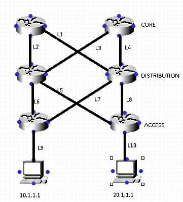
CEF switches the packets based on the routing table that is populated by the routing protocols, such as Enhanced Interior Gateway Routing Protocol (EIGRP) and Open Shortest Path First (OSPF). CEF performs load-balancing once the routing table (RIB) is calculated. In a hierarchical network design, there can be many Layer 3 (L3) equal-cost redundant paths. Consider this topology where traffic flows from the access layer across the distribution and core and into the data center.
                                         
Assume that in order to reach the network 10.1.1.1 from Router 1 (R1) [Top Left ], there are two equal-cost paths (L1 , L2). The decision about which of the two links is used is made by a hashing algorithm. By default, the Source IP (SIP) and destination IP (DIP) are used as the parameters in the hashing algorithm.
Here is a description of how the hashing algorithm works:
When there are only two paths, the switch/router performs an exclusive-OR (XOR) operation on the lower-order bits (one bit when either of two links need to be selected, two bits for 3-4 links, and so on) of the SIP and DIP. The XOR operation of the same SIP and DIP always results in the packet use of the same link.
The packet then passes onto the distribution layer, where the same hashing algorithm is used along with the same hash input, and picks a single link for all flows, which leaves the other link underutilized. This process is called CEF polarization (use of the same hash algorithm and same hash input which results in the use of a single Equal-Cost Multi-Path (ECMP) link for ALL flows).
This example illustrates this process in more detail:
                  
  1. Traffic sourced from 10.240.18.1 and destined to 10.240.20.1 enters the network at Router A and is CEF-switched. Because there are two equal-cost paths to the 10.240.20.0/24 network, the source and destination addresses in the packet go through the hash algorithm, and the result is a specific path used to reach the destination. In this case, the path the packets take is toward Router C. From there, the packets go to Router F, and on to their final destination.

  2. Traffic sourced from 10.240.18.2 and destined to 10.240.20.1 enters the network at Router A and is CEF-switched as well. Because there are two equal-cost paths to the 10.240.20.0/24 network, the source and destination addresses in the packet go through the hash algorithm, and CEF chooses a path. In this case, the path the packets take is toward Router B.

  3. Traffic sourced from 10.240.18.3 and destined to 10.240.20.1 enters the network at Router A and is also CEF-switched. Because there are two equal-cost paths to the 10.240.20.0/24 network, the source and destination addresses in the packet go through the hash algorithm, and CEF chooses a path. In this case, the path the packets take is toward Router B.

  4. The packets sourced from 10.240.18.2 and 10.240.18.3 both arrive at Router B, which again has two equal-cost paths to reach 10.240.20.1. It again runs these sets of source and destination pairs through the hash algorithm, which produces the same results that the hash algorithm on Router A produced. This means that both streams of packets pass along one path - in this case, the link toward Router E. The link toward Router D receives no traffic.

  5. After the traffic sourced from 10.240.18.2 and 10.240.18.3 is received on Router E, it is switched along the path to Router F, and then on to its final destination.

How to Avoid CEF Polarization

  1. Alternate between default (SIP and DIP) and full (SIP + DIP + Layer4 ports) hashing inputs configuration at each layer of the network.

    The Catalyst 6500 provides a few choices for the hashing algorithm:
    • Default - Use the source and destination IP address, with unequal weights given to each link in order to prevent polarization.
    • Simple - Use the source and destination IP address, with equal weight given to each link.
    • Full - Use the source and destination IP address and Layer 4 port number, with unequal weights.
    • Full Simple - Use the source and destination IP address and Layer 4 port number, with equal weights given to each link.
        6500(config)#mls ip cef load-sharing ?
          full    load balancing algorithm to include L4 ports
          simple  load balancing algorithm recommended for a single-stage CEF router
    
        6500(config)#mls ip cef load-sharing full ?
          simple  load balancing algorithm recommended for a single-stage CEF router
          <cr>
    Currently, no commands exist to check the load-sharing algorithm in use. The best way to find out which method is in use is to check the current configuration via the show running-config command. If no configuration is present starting with mls ip cef load-sharing, the default source and destination unequal weight algorithm is in use.
    Note: 1) The Catalyst 6500 does not support per packet load-sharing. 2) The full option does NOT include a universal ID in hash. If it is used at every layer of a multi-layer topology, polarization is possible. It is advisable to use the simple option with this command in order to achieve better load-sharing and to use fewer hardware adjacencies.
  2. Alternate between an even and odd number of ECMP links at each layer of the network.
    The CEF load-balancing does not depend on how the protocol routes are inserted in the routing table. Therefore, the OSPF routes exhibit the same behavior as EIGRP. In a hierarchical network where there are several routers that perform load-sharing in a row, they all use same algorithm to load-share.

    The hash algorithm load-balances this way by default:
    1: 1
    2: 7-8
    3: 1-1-1
    4: 1-1-1-2
    5: 1-1-1-1-1
    6: 1-2-2-2-2-2
    7: 1-1-1-1-1-1-1
    8: 1-1-1-2-2-2-2-2
    The number before the colon represents the number of equal-cost paths. The number after the colon represents the proportion of traffic which is forwarded per path.

    This means that:
    • For two equal cost paths, load-sharing is 46.666%-53.333%, not 50%-50%.
    • For three equal cost paths, load-sharing is 33.33%-33.33%-33.33% (as expected).
    • For four equal cost paths, load-sharing is 20%-20%-20%-40% and not 25%-25%-25%-25%.

    This illustrates that, when there is even number of ECMP links, the traffic is not load-balanced
    One way to disable CEF polarization is anti-polarization weight, which was introduced in Version 12.2(17d)SXB2.

    In order to enable anti-polarization weight, enter this command :
    6500(config)# mls ip cef load-sharing full simple
    Use this command if there are two equal cost paths and both need to be used equally. The addition of the keyword simple allows the hardware to use the same number of adjacencies as in the Cisco IOS® CEF adjacency. Without the simple keyword, the hardware installs additional adjacency entries in order to avoid platform polarization.

  3. Cisco IOS introduced a concept called unique-ID/universal-ID which helps avoid CEF polarization. This algorithm, called the universal algorithm (the default in current Cisco IOS versions), adds a 32-bit router-specific value to the hash function (called the universal ID - this is a randomly generated value at the time of the switch boot up that can can be manually controlled). This seeds the hash function on each router with a unique ID, which ensures that the same source/destination pair hash into a different value on different routers along the path. This process provides a better network-wide load-sharing and circumvents the polarization issue. This unique -ID concept does not work for an even number of equal-cost paths due to a hardware limitation, but it works perfectly for an odd number of equal-cost paths. In order to overcome this problem, Cisco IOS adds one link to the hardware adjacency table when there is an even number of equal-cost paths in order to make the system believe that there is an odd number of equal-cost links.
    In order to configure a customized value for the universal ID, use:
    6500(config)ip cef load-sharing algorithm universal <id>