Introduction
This document describes the loop prevention features and the minimum configuration steps when you run the Open Shortest Path First (OSPF) Routing Protocol between Provider Edge (PE) and Customer Edge (CE) Routers. It presents a network scenario that depicts the use of Downward Bit (DN), which is an option in the Link State Advertisement (LSA) and Domain Tag.Prerequisites
Requirements
Cisco recommends that you have knowledge of OSPF and Multiprotocol Label Switching (MPLS) Layer 3 VPN.Components Used
This document is not restricted to specific software and hardware versions.The information in this document was created from the devices in a specific lab environment. All of the devices used in this document started with a cleared (default) configuration. If your network is live, make sure that you understand the potential impact of any command.
Background Information
The Service Provider (SP) and the CE Router exchange routes with a routing protocol to which the SP and and Customer jointly agree. The scope of this document is to describe the loop-prevention mechanism when OSPFv2 is used.When OSPFv2 is used on a PE-CE link that belongs to a particular Virtual Routing and Forwarding (VRF) or VPN, the PE router:
- Redistributes the routes received via OSPF for that VPN into Multiprotocol-Border Gateway Protocol (MP-BGP) and advertises it to the other PE routers.
- Redistributes the BGP routes intalled in the VPN via MP-BGP into the OSPF Instance for that VPN and advertises it to the CE Routers.
Configure
Network Diagram
Consider this network topology in order to understand the loop-prevention techniques.
In this setup, there is a possibility of a loop. For example, if CE1 advertises the OSPF LSA Type 1 to PE1, which redistributes the route into VPNv4 and advertises it to PE2, then PE2 in turn advertises the Summary LSA to CE2. This route received by CE2 could be advertised back to PE3. The third PE router learns the OSPF route, which is better than the BGP route, and re-advertises the route into BGP as local to the Customer Site 2. PE3 never learns that the route that was advertised was not originated from Customer Site 2.
In order to overcome this situation, when the routes are redistributed from MP-BGP into OSPF, then they are marked with a DN Bit in LSA Type 3, 5, or 7 and have the domain tag for Type 5 and 7 LSA.
Configurations
Here is the sample configuration on PE routers. This configuration includes the VRF configuration, the OSPF Process 2 that runs between the PE-CE Routers, the OSPF Process 1 that runs as Interior Gateway Protocol ( IGP) in the MPLS Core, and the MP-BGP configuration.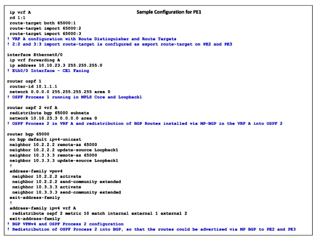
DN Bit
The previously unused bit in the OSPF LSA Options Field is referred to as the DN Bit. This bit is set on Type 3, 5, and 7 LSA when the MP-BGP routes are redistributed into OSPF. When the other PE Router receives the LSA from a CE router Type 3, 5, or 7 LSA with the DN Bit set, the information from that LSA is not used in the OSPF route calculation.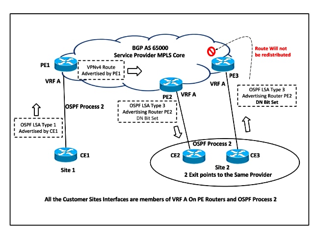
Based on the network topology, PE2 sets the DN Bit for the redistributed LSA and this LSA is never considered for route calculation in OSPF Process 2 on PE3. So PE3 never redistributes this route back into MP-BGP.
Here is an example of the OSPF Header that shows the DN Bit Set, when the route was advertised by PE Router for Type 3 LSA:
Open Shortest Path First
    OSPF Header
        Version: 2
        Message Type: LS Update (4)
        Packet Length: 56
        Source OSPF Router: 10.10.23.3 (10.10.23.3)
        Area ID: 0.0.0.0 (0.0.0.0) (Backbone)
        Checksum: 0x4034 [correct]
        Auth Type: Null (0)
        Auth Data (none): 0000000000000000
    LS Update Packet
        Number of LSAs: 1
        Summary-LSA (IP network)
            .000 1110 0001 0000 = LS Age (seconds): 3600
            0... .... .... .... = Do Not Age Flag: 0
            Options: 0xa2 (DN, DC, E)
                1... .... = DN: Set
                .0.. .... = O: Not set
                ..1. .... = DC: Demand Circuits are supported
                ...0 .... = L: The packet does NOT contain LLS data block
                .... 0... = NP: NSSA is NOT supported
                .... .0.. = MC: NOT Multicast Capable
                .... ..1. = E: External Routing Capability
                .... ...0 = MT: NO Multi-Topology Routing
Domain Tag
The Domain Tag is applicable only for the OSPF Type 5 and Type 7 LSA. When the VPNv4 routes are redistributed from MP-BGP into OSPF on PE Router, the Domain Tag is set for OSPF External Routes. The tag could either be manuallly set with the domain-tag command under OSPF Process or a 32-bit value can be automatically generated: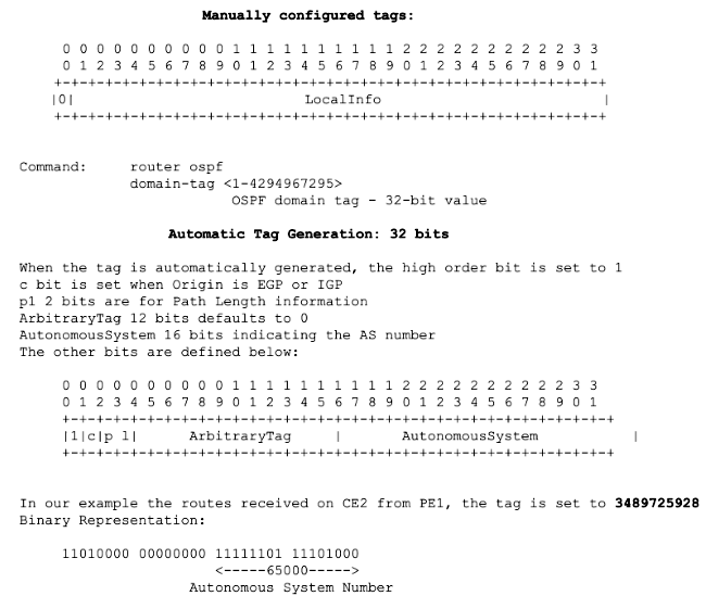
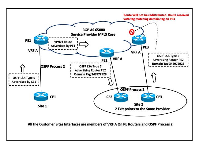
Based on the network topology, PE2 sets the Domain Tag for Type 5 and Type 7 LSA when it redistributes the VPNv4 route into OSPF. This LSA is never considered for route calculation because the DN Bit is already set, but it also has the Domain Tag set, so the LSA is ignored because the Domain Tag matches the VPN / VRF Tag. Hence the route is never redistributed into OSPF.
This example shows LSA Type 5 ignored when it is received with the Domain Tag Set the same as the local VRF Domain Tag on PE3 from CE3:
*Jan 31 00:29:23.947: OSPF-2 EXTER:  adv_rtr 10.10.57.5, age 3, seq 0x80000001,
metric 10, metric-type 2, fw-addr 0.0.0.0
*Jan 31 00:29:23.947: OSPF-2 EXTER: Tag equals to VPN Tag, ignoring the LSA
*Jan 31 00:29:23.947: OSPF-2 EXTER: Process partial nssa spf queue

PE3#show ip ospf database external 192.168.5.5

            OSPF Router with ID (10.3.3.3) (Process ID 1)

            OSPF Router with ID (10.10.68.6) (Process ID 2)

                Type-5 AS External Link States

  LS age: 38
  Options: (No TOS-capability, DC)
  LS Type: AS External Link
  Link State ID: 192.168.5.5 (External Network Number )
  Advertising Router: 10.10.57.5
  LS Seq Number: 80000001
  Checksum: 0x89A3
  Length: 36
  Network Mask: /32
        Metric Type: 2 (Larger than any link state path)
        MTID: 0
        Metric: 10
        Forward Address: 0.0.0.0
        External Route Tag: 3489725928
Verify
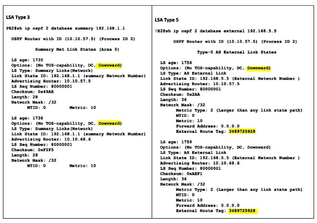
The commands to discover if the DN Bit is set for the LSA and the Domain Tag applied are the same that are used in order to check the LSA Database.This output shows the example for OSPF Type 3 and Type 5 LSA and highlights the DN Bit and Tag Set when the VPNv4 routes are redistributed into OSPF on PE2:
THE DOWN BIT _________________
consider / \
/ \
CE------\-PE1---------------PE2------------/--CE2 |
| | ospf domain |
| | /
PE 2.1---------/--CE2.1 /
\__________________/
when the router CE advertise a route to PE1, the route gets redistributed into mpbgp, and
when PE2 receives it, its redistributed into ospf domain, and at PE2.1 the same ospf route
is again redistributed into mpbgp, and this causes a loop
>> to save this problem, a DOWN BIT is defined in the OSPF LSA, and this bit is set whenever a MPBGP route is redistributed into ospf domain, and the PE router never redistributes a OSPF route with DOWN bit set to MPBGP, therefore essentially preventing the loop.
>> THE ROUTING BIT IS NOT SET ON ROUTES WITH DOWN BIT SET. AND THIS ROUTING BIT IS USED INTERNALLY AND IS NOT PROPAGATED IN UPDATES AND THESE ROUTES NEVER ENTER THE ROUTING TABLE.
>> Also the DOWN bit is cleared when the route is adverised out a ospf domain to different ospf domain. so, there are chances this same route gets redistributed into the mpbgp and CAUSING A LOOP , at somewhere else, so, therefore to prevent this ROUTE-TAGS are used.
.>>how tags work
when the PE router redistributes the mpbgp route into ospf, in addition to setting the down bit, it also adds a TAG value equal to the BGP AS no, to that route, now after the route has been redistributed into the ospf domain, with down bit set and the tag value put, and if this route now is advertised to a different ospf domain, as en external route ofcourse, the down bit will be removed but the tag is carried along, and when this route comes to the PE in that domain to get redistributed into the mPbgp the PE router checks the tag, value, if the tag value is same as the BgpAS no then the route is no redistributed.
some people mentioned
Both the OSPF (Down-Bit) and (Domain-Tag) Prevents OSPF routing loop. Although these features may look Same but there is a Major different implementation Scenario where the (Down-Bit) wont prevent loop and the (Domain-Tag) would be the right choice.
Here is the difference:
Down-Bit
:- The (Down-Bit) is an Option in the LSA Header, its set whenever
the Route is redistributed from MPBGP to OSPF, It ensures the same route
is never back to the same OSPF Source originating it. In a Dual Homed
Scenario to the Same MPLS Provider, the CE might send the same route
back to the provider and without the (Down-Bit) Option , A Loop woud
Occur.
However,
The (Down-Bit) Option will not prevent a Loop incase the Route traverse
more than a Single MPLS Provider. Meaning, if there is a CE dual homed
to Two different MPLS Service Providers , and those Providers are
interconnected using (Inter-as) Architecture Approach, the Down-Bit Will
not Prevent the Loop. Here came the Need for (OSPF Domain-Tag) where
this Option is primarily used in such situation to ensure the OSPF
domain-Tag is preserved unique a cross different ***. So whenever the
route is back by different AS , the Original MPLS Provider which source
the update reject the route since the (Domain-Tag) feature is set.
consider / \
/ \
CE------\-PE1---------------PE2------------/--CE2 |
| | ospf domain |
| | /
PE 2.1---------/--CE2.1 /
\__________________/
when the router CE advertise a route to PE1, the route gets redistributed into mpbgp, and
when PE2 receives it, its redistributed into ospf domain, and at PE2.1 the same ospf route
is again redistributed into mpbgp, and this causes a loop
>> to save this problem, a DOWN BIT is defined in the OSPF LSA, and this bit is set whenever a MPBGP route is redistributed into ospf domain, and the PE router never redistributes a OSPF route with DOWN bit set to MPBGP, therefore essentially preventing the loop.
>> THE ROUTING BIT IS NOT SET ON ROUTES WITH DOWN BIT SET. AND THIS ROUTING BIT IS USED INTERNALLY AND IS NOT PROPAGATED IN UPDATES AND THESE ROUTES NEVER ENTER THE ROUTING TABLE.
>> Also the DOWN bit is cleared when the route is adverised out a ospf domain to different ospf domain. so, there are chances this same route gets redistributed into the mpbgp and CAUSING A LOOP , at somewhere else, so, therefore to prevent this ROUTE-TAGS are used.
.>>how tags work
when the PE router redistributes the mpbgp route into ospf, in addition to setting the down bit, it also adds a TAG value equal to the BGP AS no, to that route, now after the route has been redistributed into the ospf domain, with down bit set and the tag value put, and if this route now is advertised to a different ospf domain, as en external route ofcourse, the down bit will be removed but the tag is carried along, and when this route comes to the PE in that domain to get redistributed into the mPbgp the PE router checks the tag, value, if the tag value is same as the BgpAS no then the route is no redistributed.
some people mentioned
Both the OSPF (Down-Bit) and (Domain-Tag) Prevents OSPF routing loop. Although these features may look Same but there is a Major different implementation Scenario where the (Down-Bit) wont prevent loop and the (Domain-Tag) would be the right choice.