Tuesday, 22 March 2016

BGP additional path

Configuring BGP Additional Paths

We will describes how to configure additional paths for the Border Gateway Protocol (BGP).
This chapter includes the following sections:

Information About BGP Additional Paths

This section includes the following topics:

Overview

BGP routers and route reflectors (RRs) propagate only their best paths over their sessions. The advertisement of a prefix replaces the previous announcement of that prefix (this behavior is known as an implicit withdraw). The implicit withdraw can achieve better scaling, but at the cost of path diversity.
Path hiding can prevent efficient use of BGP multipath, prevent hitless planned maintenance, and lead to multi-exit discriminator (MED) oscillations and suboptimal hot-potato routing. In a next-hop failure, path hiding inhibits fast and local recovery because the network has to wait for BGP control plane convergence to restore traffic. The BGP Additional Paths feature offers path diversity; the best external or best internal features offer path diversity in limited scenarios.
The BGP Additional Paths feature allows multiple paths for the same prefix to be advertised without the new paths implicitly replacing the previous paths. Path diversity is achieved instead of path hiding.

Path-Hiding Scenario

The following figure shows prefix p with paths p1 and p2 advertised from BR1 and BR4 to RR1. RR1 selects the bes tpath of the two and then advertises only p1 to the PE.
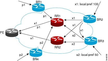
Figure 9-1 RR Hiding an Additional Path
In the above figure, prefix x with path x1 is advertised from BR2 to BR3 (which has path x2) with local preference 100. BR3 also has path x2, but due to the routing policy, BR3 advertises to the RRs x1 (not shown) instead of x2, x2 is suppressed. You could turn on the advertisement of best external on BR3 and advertise x2 to the route reflectors (RRs), but, the RRs advertise only the best path.

Suboptimal Hot-Potato Routing Scenario

To minimize internal transport costs, transit Internet service providers try to forward packets to the closest exit point (according to the Interior Gateway Protocol (IGP) cost). This behavior is known as hot-potato routing. In the distributed RR cluster model of the figure below, assume traffic that is coming from LA must go to Mexico. All links have the same IGP cost. If there are two exit points toward Mexico—one toward Austin and one toward Atlanta—the border router will try to send traffic to Austin based on the lower IGP cost from LA toward Austin than toward Atlanta. In a centralized RR model where the central RR resides where RR3 is (and RR1, RR2, RR4, and RR5 do not exist), the closest exit point toward Mexico, as seen from RR3, might be Atlanta. Sending the traffic from LA toward the Atlanta border router (BR) results in suboptimal hot-potato routing and is not desirable.
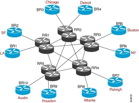
Figure 9-2 Distributed RR Cluster
 

Benefits of Additional BGP Paths

BGP routers and route reflectors (RR) propagate only their best path over their sessions. The advertisement of a prefix replaces the previous announcement of that prefix (also known as an implicit withdraw).
While this behavior might achieve better scaling, it can prevent path diversity, which tends to be poor or completely lost. This behavior prevents efficient use of the BGP multipath, prevents hitless planned maintenance, and lead to multi-exit discriminator (MED) oscillations and suboptimal hot-potato routing. It also inhibits fast and local recovery for next-hop failures, because the network has to wait for BGP control plane convergence to restore traffic.
The BGP Additional Paths feature is a BGP extension that allows the advertisement of multiple paths for the same prefix without the new paths implicitly replacing any previous paths. This behavior promotes path diversity and reduces MED oscillations.

BGP Additional Paths Functionality

You can use the BGP Additional Paths feature by adding a path identifier to each path in the Network Layer Reachability Information (NLRI). The path identifier (ID) can be considered as something similar to a route distinguisher (RD) in virtual private networks (VPNs), except that a path ID can apply to any address family. Path IDs are unique to a peering session and are generated for each network. The path identifier is used to prevent a route announcement from implicitly withdrawing the previous one. The Additional Paths feature allows the advertisement of more paths, in addition to the best path and allows the advertisement of multiple paths for the same prefix, without the new paths implicitly replacing any previous paths.
The BGP Additional Paths feature requires you to take general steps:
1. Specify whether the device can send, receive, or send and receive additional paths at the address family level or the neighbor level. During session establishment, two BGP neighbors negotiate the additional path capabilities (whether they can send or receive) between them.
2. Select a set or sets of candidate paths for advertisement by specifying the selection criteria.
3. Advertise for a neighbor a set or sets of additional paths from the candidate paths marked.
To send or receive additional paths, the additional path capability must be negotiated between the neighbors. If no negotiation occurs, even if the selection criteria marks the best path and the neighbor is configured to advertise the marked paths, the selections are useless because only the best path is advertised.
Configuring BGP to send or receive additional paths triggers negotiation of an additional path’s capability with the device's peers. Neighbors that have negotiated the capability are grouped together in an update group (if other update group policies allow), and in a separate update group from those peers that have not negotiated the capability. Therefore, the additional path capability causes the neighbor's update group membership to be recalculated.

Additional Path Selection

Only the best path is advertised to peers unless you configure the set path-selection all advertise command which advertises all BGP paths as additional paths to peers if the receive capability is enabled.

Advertising a Subset of the Paths Selected

Take care when you select a set of paths but want to advertise a different set of paths. If the set of paths you want to advertise is not a subset of the selected paths, you will not advertise the paths that you want advertised.

Guidelines and Limitations

Configuring BGP Additional Paths has the following guidelines and limitations:
  • BGP add-path is not supported as a dynamic capability. It is included in the OPEN message, but not in CAPABILITY message. The configuration takes effect when the next session is established and does not cause established sessions to get torn down.

Configuring BGP Additional Paths

This section includes the following topics:

Configuring BGP Additional Paths for each Address Family

You can specify whether the device can send and receive additional paths to and from all neighbors within an address family.

BEFORE YOU BEGIN

Ensure that you have enabled the BGP feature.

SUMMARY STEPS

1. configure terminal
2. router bgp as-number
3. address family {ipv4 | ipv6} unicast
4. additional-paths receive
5. additional-paths send
6. additional-paths selection route-map map-name
7. end

DETAILED STEPS


Command
Purpose
Step 1
configure terminal
 
Example :
switch# configure terminal
switch(config)#
Enters global configuration mode.
Step 2
router bgp as-number
 
Example :
switch(config)# router bgp 65000
switch(config-router)#
Enables BGP and assigns the autonomous system number to the local BGP speaker.
Step 3
address family {ipv4 | ipv6} unicast
 
Example :
switch(config-router)# address family ipv6 unicast
Enters address family configuration mode.
Step 4
additional-paths receive
 
Example :
switch(config-router-af)# additional-paths receive
(Optional) Enables BGP additional paths for a prefix to be received from a capable peer.

Note This capability applies to all neighbors under the specified address family unless the capability is explicitly disabled with the neighbor additional-paths receive disable command, which overrides the configuration for the address family.

Step 5
additional-paths send
 
Example :
switch(config-router-af)# additional-paths send
(Optional) Enables BGP additional paths for a prefix to be sent to a capable peer.

Note This capability applies to all neighbors under the specified address family unless the capability is explicitly disabled with the neighbor additional-paths send disable command, which overrides the configuration for the address family.

Step 6
additional-paths selection route-map map-name
 
Example :
switch(config-router-af) # additional-paths selection route-map rmap
(Optional) Configures additional paths selection capability for a prefix.
Step 7
end
 
Example:
switch(config-router-af)# end
(Optional) Exits to privileged EXEC mode.

Configuring BGP Additional Paths for each Neighbor

You can configure whether a particular neighbor can send or receive additional paths.

BEFORE YOU BEGIN

Ensure that you have enabled the BGP feature (see the “Enabling the BGP Feature” section).

SUMMARY STEPS

1. configure terminal
2. router bgp as-number
3. neighbor { ipv4-address | ipv4-prefix/length | ipv6-address | ipv6-prefix/length } [ remote-as { as-num } [. as-num ]]
4. address family {ipv4 | ipv6} unicast
5. capability additional-paths receive [disable]
6. capability additional-paths send [disable]
7. end

DETAILED STEPS


Command
Purpose
Step 1
configure terminal
 
Example :
switch# configure terminal
switch(config)#
Enters global configuration mode.
Step 2
router bgp as-number
 
Example :
switch(config)# router bgp 65000
switch(config-router)#
Enables BGP and assigns the autonomous system number to the local BGP speaker.
Step 3
neighbor {ipv4-address | ipv4-prefix/length | ipv6-address
| ipv6-prefix/length} [ remote-as {as-num} [.as-num ]]
 
Example :
switch(config-router)# neighbor 2001:DB8::1037
Configures a BGP neighbor (router, VRF) and enters neighbor configuration mode.
Step 4
address family {ipv4 | ipv6} unicast
 
Example :
switch(config-router)# address family ipv6 unicast
Enters address family configuration mode.
Step 5
capability additional-paths receive [disable]
 
Example :
switch(config-router-af)# capability additional-paths receive
(Optional) Configures the receive additional paths capability for the specified neighbor.

Note This command overrides any send or receive capability that is configured at the address-family level.

Step 6
capability additional-paths send [disable]
 
Example :
switch(config-router-af)# capability additional-paths send
(Optional) Configures the send additional paths capability for the specified neighbor.

Note This command overrides any send or receive capability that is configured at the address-family level.

Step 7
end
 
Example:
switch(config-router-af)# end
(Optional) Exits to privileged EXEC mode.

Configuring Additional Paths Using a Peer Policy Template

You can send and receive additional paths by using a peer policy template.

BEFORE YOU BEGIN

Ensure that you have enabled the BGP feature (see the “Enabling the BGP Feature” section).

SUMMARY STEPS

1. configure terminal
2. router bgp as-number
3. template peer-policy template-name
4. capability additional-paths receive [disable]
5. capability additional-paths send [disable]
6. exit
7. neighbor { ipv4-address | ipv4-prefix/length | ipv6-address | ipv6-prefix/length } [ remote-as { as-num } [. as-num ]]
8. inherit peer-policy template-name sequence-number
9. end

DETAILED STEPS


Command
Purpose
Step 1
configure terminal
 
Example :
switch# configure terminal
switch(config)#
Enters global configuration mode.
Step 2
router bgp as-number
 
Example :
switch(config)# router bgp 65000
Enters BGP mode and assigns the autonomous system number to the local BGP speaker.
Step 3
template peer-policy template-name
 
Example :
switch(config-router)# template peer-policy rr-client-ptl #
Enters policy-template configuration mode and creates a peer policy template.
Step 4
capability additional-paths receive [disable]
 
Example :
switch(config-router-af)# capability additional-paths receive
(Optional) Configures the receive additional paths capability for the specified neighbor.

Note This command overrides any send or receive capability that is configured at the address-family level.

Step 5
capability additional-paths send [disable]
 
Example :
switch(config-router-af)# capability additional-paths send
(Optional) Configures the send additional paths capability for the specified neighbor.

Note This command overrides any send or receive capability that is configured at the address-family level.

Step 6
exit
 
Example :
switch(config-router-ptmp)# exit
 
Exits policy-template configuration mode and returns to router configuration mode.
Step 7
neighbor {ipv4-address | ipv4-prefix/length | ipv6-address
| ipv6-prefix/length} [ remote-as {as-num} [.as-num]]
 
Example :
switch(config-router)# neighbor 2001:DB8::1037
Configures a BGP neighbor (router, VRF) and enters neighbor configuration mode.
Step 8
address-family ipv4 unicast
 
Example :
switch(config-router-neighbor)# address-family ipv4 unicast
switch(config-router-neighbor-af)#
(Optional) Configures global address family configuration mode for the specified address family.
Step 9
inherit peer-policy template-name sequence-number
 
Example :
switch(config-router-neighbor-af)# inherit peer-policy rr-client-ptl 10
Sends a peer policy template to a neighbor so that the neighbor can inherit the configuration.
Step 10
end
 
Example:
switch(config-router-af)# end
(Optional) Exits to privileged EXEC mode.

Filtering and Setting Actions for Additional Paths

You can optionally use a route map to filter the paths to be advertised by matching on the prefix of additional paths that are candidates to be advertised. (These prefixes are configured with the additional-paths selection command.)
You can also optionally set one or more actions to take for those paths that pass through the route map. This procedure uses the set metric command. Other set commands are available that are not shown in this task.
You would set a metric for paths marked with all (all paths with a unique next-hop) if the neighbor is receiving the same routes from its neighbors. Suppose the neighbor 2001:DB8::1037 is receiving the same route from different neighbors. Routes received from the local device have a metric of 565 and routes from another device have a metric of 700. Routes with metric 565 have precedence over the routes with metric 700.

SUMMARY STEPS

1. configure terminal
2. route-map route-name [ deny | permit ] [ sequence-number ]
3. set path-selection all advertise
4. set metric metric-value
5. end

DETAILED STEPS

:
Command
Purpose
Step 1
configure terminal
 
Example :
switch# configure terminal
switch(config)#
Enters global configuration mode.
Step 2
route-map map-name [ deny | permit ] [ sequence-number ]
 
Example :
switch(config)# route-map add_path4 permit 10
Defines a route map and the conditions for redistributing routes from one routing protocol into another.
Step 3
set path-selection all advertise
 
Example :
switch(config-route-map)# set path-selection all advertise
Advertises all BGP paths as additional paths to peers if the receive capability is enabled.
Step 4
set metric metric-value
 
Example :
switch(config-route-map)# set metric 500
Sets the metric of the additional paths that pass the match criteria.
  • Other set commands can be used to take action on the paths that pass the route map.
Step 5
end
 
Example:
switch(config-router-af)# end
(Optional) Exits to privileged EXEC mode.

Configuration Examples for BGP Additional Paths

This section includes the following topics:

BGP Additional Paths Send and Receive Capabilities

R1

In this example, R1's address is 2001:db8::1045; its neighbor R2 has an address of 2001:db8::1037. Updates are sent from R2 to R1 with additional-paths (all paths advertised). Updates are sent from R1 to R2 with only the classic BGP best path advertised because R2 can only send additional paths, not receive additional paths.
route-map add_path4 permit 10
set metric 500
set path-selection all advertise
!!
router bgp 1
address-family ipv6 unicast
additional-paths send
additional-paths receive
additional-paths selection route-map add_path4
neighbor 2001:db8::1037
address-family ipv6 unicast
capability additional-paths send
capability additional-paths receive

R2

route-map add_path4 permit 10
set metric 500
set path-selection all advertise
!!
router bgp 2
address-family ipv6 unicast
additional-paths selection route-map add_path4
neighbor 2001:db8::1045
address-family ipv6 unicast
capability additional-paths send

BGP Additional Paths Using a Peer Policy Template

This example shows that the neighbor with IP address 2001:db8::1037 has the send and receive capability for additional paths enabled through the template named rr-client-pt1:
router bgp 65000
address-family ipv6 unicast
additional-paths send
additional-paths receive
additional-paths selection route-map add_path4
neighbor 2001:db8::1037
address-family ipv6 unicast
inherit peer-policy rr-client-pt1 10
template peer-policy rr-client-pt1
capability additional-paths send
capability additional-paths receive

Verifying the BGP Additional Paths Configuration

To display information about the BGP additional paths configuration, perform the following tasks:
 
Command
Purpose
show ip bgp [ip-address]
Displays entries in the BGP table.
show ip bgp neighbors [ip-address [ advertise-routes ]]
Displays the configured neighbors and the other information specific to individual neighbor.

Thursday, 17 March 2016

Best path selection in different OSPF process ID

Best Path Selection from different OSPF Process ID

When two OSPF processes are configured on a router and if same prefix is received on both OSPF process, it will be treated as like received from two different routing protocol and metric/LSA type will be ignored. Selection will be purely based on administrative distance. If the administrative distance is same, Router appears to select the best path based on lowest process ID.
The below topology has been configured to run OSPF process 1 and 100 on both R1 and R2.


The above statement has been tested by two test cases,
Test Case 1 :
Loopback 2 on R2 is redistributed into process 123 and configured with “network 22.22.22.0 0.0.0.255 area 0 “ into process 1.
R2#show run | sec ospf
router ospf 1
router-id 150.1.2.2
log-adjacency-changes
network 22.22.22.2 0.0.0.0 area 0
network 150.1.12.2 0.0.0.0 area 0
router ospf 123
router-id 2.2.2.2
log-adjacency-changes
redistribute connected subnets route-map CONN2OSPF
network 150.1.21.2 0.0.0.0 area 0
R2#
R2#route-map CONN2OSPF permit 10
match interface Loopback2
R2#
On R1, it can be confirmed that 22.22.22.0/24 is received as Type 1 LSA (router) via process 1 and Type 5 LSA (external) via process 123,

R1#show ip ospf database router 150.1.2.2 | inc Process|22.22
OSPF Router with ID (1.1.1.1) (Process ID 123)
OSPF Router with ID (150.1.1.1) (Process ID 1)
(Link ID) Network/subnet number: 22.22.22.2
R1#show ip ospf database external 22.22.22.0
OSPF Router with ID (1.1.1.1) (Process ID 123)
Type-5 AS External Link States
Routing Bit Set on this LSA
LS age: 1788
Options: (No TOS-capability, DC)
LS Type: AS External Link
Link State ID: 22.22.22.0 (External Network Number )
Advertising Router: 2.2.2.2
LS Seq Number: 80000001
Checksum: 0x90C5
Length: 36
Network Mask: /24
Metric Type: 2 (Larger than any link state path)
TOS: 0
Metric: 20
Forward Address: 0.0.0.0
External Route Tag: 0
OSPF Router with ID (150.1.1.1) (Process ID 1)
R1#
On R1, it is observed that route from process ID of numerically less number is preferred. In our case, Type 1 LSA from OSPF process 1 is selected and installed in routing table.
Clearing the routing table or clearing OSPF process doesn’t make any difference.

R1#show ip route 22.22.22.0
Routing entry for 22.22.22.0/24
Known via "ospf 1", distance 110, metric 11, type intra area
Last update from 150.1.12.2 on Ethernet0/0.12, 00:00:17 ago
Routing Descriptor Blocks:
* 150.1.12.2, from 150.1.2.2, 00:00:17 ago, via Ethernet0/0.12
Route metric is 11, traffic share count is 1
R1#
R1#clear ip route *
R1#clear ip ospf process
Reset ALL OSPF processes? [no]: yes
R1#show ip route 22.22.22.0
% Network not in table
R1#show ip route 22.22.22.0
Routing entry for 22.22.22.0/24
Known via "ospf 1", distance 110, metric 11, type intra area
Last update from 150.1.12.2 on Ethernet0/0.12, 00:00:03 ago
Routing Descriptor Blocks:
* 150.1.12.2, from 150.1.2.2, 00:00:03 ago, via Ethernet0/0.12
Route metric is 11, traffic share count is 1
R1#
Test Case 2:
Loopback 2 on R2 is redistributed into process 1 and configured with “network 22.22.22.0 0.0.0.255 area 0 “ into process 123.

R2#show run | sec ospf
router ospf 1
router-id 150.1.2.2
log-adjacency-changes
redistribute connected subnets route-map CONN2OSPF
network 150.1.12.2 0.0.0.0 area 0
router ospf 123
router-id 2.2.2.2
log-adjacency-changes
network 22.22.22.2 0.0.0.0 area 0
network 150.1.21.2 0.0.0.0 area 0
R2#
On R1, it can now be observed that 22.22.22.0/24 is received as Type 1 LSA (router) via OSPF process 123 and Type 5 LSA (external) via OSPF process 1 as below,

R1#show ip ospf database router | inc Process|22.22.
OSPF Router with ID (1.1.1.1) (Process ID 123)
(Link ID) Network/subnet number: 22.22.22.0
OSPF Router with ID (150.1.1.1) (Process ID 1)
OSPF Router with ID (10.1.14.1) (Process ID 45)
R1#
R1#show ip ospf database external 22.22.22.0
OSPF Router with ID (1.1.1.1) (Process ID 123)
OSPF Router with ID (150.1.1.1) (Process ID 1)
Type-5 AS External Link States
Routing Bit Set on this LSA
LS age: 117
Options: (No TOS-capability, DC)
LS Type: AS External Link
Link State ID: 22.22.22.0 (External Network Number )
Advertising Router: 150.1.2.2
LS Seq Number: 80000001
Checksum: 0x5F63
Length: 36
Network Mask: /24
Metric Type: 2 (Larger than any link state path)
TOS: 0
Metric: 20
Forward Address: 0.0.0.0
External Route Tag: 0
OSPF Router with ID (10.1.14.1) (Process ID 45)
R1#
On R1, it is observed that route from process ID of numerically less number is preferred. In our case, Type 5 LSA from OSPF process 1 is selected and installed in routing table.

Clearing the routing table or clearing OSPF process doesn’t make any difference.

R1#show ip route 22.22.22.0
Routing entry for 22.22.22.0/24
Known via "ospf 1", distance 110, metric 20, type extern 2, forward metric 10
Last update from 150.1.12.2 on Ethernet0/0.12, 00:03:17 ago
Routing Descriptor Blocks:
* 150.1.12.2, from 150.1.2.2, 00:03:17 ago, via Ethernet0/0.12
Route metric is 20, traffic share count is 1
R1#
R1#clear ip route *
R1#clear ip ospf pro
Reset ALL OSPF processes? [no]: yes
R1#
R1#show ip route 22.22.22.0
% Network not in table
R1#show ip route 22.22.22.0
% Network not in table
R1#show ip route 22.22.22.0
Routing entry for 22.22.22.0/24
Known via "ospf 1", distance 110, metric 20, type extern 2, forward metric 10
Last update from 150.1.12.2 on Ethernet0/0.12, 00:00:00 ago
Routing Descriptor Blocks:
* 150.1.12.2, from 150.1.2.2, 00:00:00 ago, via Ethernet0/0.12
Route metric is 20, traffic share count is 1
R1#
Testcase 3:
Now let us try test case 2 setup, but allow route received from Process ID 123 to be installed in routing table and then advertise same prefix via OSPF process 1.
I have shut the interface connected & Configured for OSPF Process 1 and receive route 22.22.22.0/24 only from Process 123.

R1#conf t
Enter configuration commands, one per line. End with CNTL/Z.
R1(config)#int e0/0.12
R1(config-subif)#shut
R1(config-subif)#
R1(config-subif)#do sh ip ospf data router | in Proce|22.22.22.
OSPF Router with ID (150.1.1.1) (Process ID 123)
(Link ID) Network/subnet number: 22.22.22.0
OSPF Router with ID (1.1.1.1) (Process ID 1)
OSPF Router with ID (10.1.14.1) (Process ID 45)
R1(config-subif)#do sh ip ospf data external 22.22.22.0
OSPF Router with ID (150.1.1.1) (Process ID 123)
OSPF Router with ID (1.1.1.1) (Process ID 1)
OSPF Router with ID (10.1.14.1) (Process ID 45)
R1(config-subif)#do show ip route 22.22.22.2
Routing entry for 22.22.22.0/24
Known via "ospf 123", distance 110, metric 2, type intra area
Last update from 150.1.21.2 on Ethernet0/0.21, 00:02:55 ago
Routing Descriptor Blocks:
* 150.1.21.2, from 2.2.2.2, 00:02:55 ago, via Ethernet0/0.21
Route metric is 2, traffic share count is 1
R1(config-subif)#
Now, I will un shut the interface and receive route 22.22.22.0/24 from Process 1.

R1(config)#int e0/0.12
R1(config-subif)#no shut
R1(config-subif)#do sh ip ospf data router | inc Proce|22.22.22.
OSPF Router with ID (150.1.1.1) (Process ID 123)
(Link ID) Network/subnet number: 22.22.22.0
OSPF Router with ID (1.1.1.1) (Process ID 1)
OSPF Router with ID (10.1.14.1) (Process ID 45)
R1(config-subif)#do sh ip ospf database external 22.22.22.0
OSPF Router with ID (150.1.1.1) (Process ID 123)
OSPF Router with ID (1.1.1.1) (Process ID 1)
Type-5 AS External Link States
Routing Bit Set on this LSA
LS age: 510
Options: (No TOS-capability, DC)
LS Type: AS External Link
Link State ID: 22.22.22.0 (External Network Number )
Advertising Router: 150.1.2.2
LS Seq Number: 80000013
Checksum: 0x3B75
Length: 36
Network Mask: /24
Metric Type: 2 (Larger than any link state path)
TOS: 0
Metric: 20
Forward Address: 0.0.0.0
External Route Tag: 0
OSPF Router with ID (10.1.14.1) (Process ID 45)
R1(config-subif)#
It still can be observed that OSPF route from Process 123 is not preempted by route from Process 1.

When routing table is cleared, route from Process 1 will be installed.

R1#show ip route 22.22.22.2
Routing entry for 22.22.22.0/24
Known via "ospf 123", distance 110, metric 2, type intra area
Last update from 150.1.21.2 on Ethernet0/0.21, 00:07:18 ago
Routing Descriptor Blocks:
* 150.1.21.2, from 2.2.2.2, 00:07:18 ago, via Ethernet0/0.21
Route metric is 2, traffic share count is 1
R1#clear ip route *
R1#show ip route 22.22.22.2
Routing entry for 22.22.22.0/24
Known via "ospf 1", distance 110, metric 20, type extern 2, forward metric 10
Last update from 150.1.12.2 on Ethernet0/0.12, 00:00:01 ago
Routing Descriptor Blocks:
* 150.1.12.2, from 150.1.2.2, 00:00:01 ago, via Ethernet0/0.12
Route metric is 20, traffic share count is 1
R1#
Tried with modifying the router-id and it still it appears to select the route based on lowest process ID.

Conclusion:
The above testing appears that when a router running 2 OSPF processes receives same prefix from different process, it will ignore metric/LSA Type and will only check the Administrative Distance (AD). If both are same, it will install based on lowest process ID.

In case, we receive the prefix via highest process ID and already installed in routing table, it will not be preempted by the lowest process ID until you clear the routing table

If we have for example OSPF, this is how a route gets selected to the RIB(global).
The routers exchange LSAs with each other. Within an area every router has the same
view of the network. These LSAs populate the LSDB. If there are multiple paths to
a destination they will compete with each other unless they are of same type and equal
cost. Intra area is preferred first, then inter and finally external routes. There is no
way of modifying this behaviour. The best route then goes to the OSPF RIB, could be several
if they are equal. From there this route will compete with other routing protocols and the
AD will decide which one is installed. If the OSPF one is best then that one goes to the global
RIB. Then finally the RIB populates FIB with this information and forwarding can ensue.
This is a picture I made that describes the process.
Route_selection

IP switching per-packet and per-destination

IP switching is the internal mechanism used by Cisco IOS to forward packets through a router. Available mechanisms include process switching, fast switching, and Cisco Express Forwarding. Depending on which of the three mechanisms is used to switch the majority of packets, the overall system performance and load balancing is affected.
IP switching mechanisms support two general modes, per-packet and per-destination. The following table outlines the advantages and disadvantages of both modes.
Per-Destination Per-Packet
IP Switching Mechanism Fast switching and Cisco Express Forwarding per-destination. Process switching and Cisco Express Forwarding per-packet.
Advantages With fast switching, packets for a given destination are guaranteed to take the same path even if multiple paths are available. With Cisco Express Forwarding switching, packets for a given source-destination host pair are guaranteed to take the same path, even if multiple paths are available. Traffic destined for different pairs tend to take different paths. Path utilization with per-packet load balancing is good because per-packet load balancing allows the router to send successive data packets over paths without regard to individual hosts or user sessions. It uses the round-robin method to determine which path each packet takes to the destination
Disadvantages With fast switching, per destination switching may result in unequal load sharing because packets to one destination always follow the same path. Cisco Express Forwarding switching may result in unequal distribution with a small number of source-destination pairs. Per-destination load balancing depends on the statistical distribution of traffic; load sharing becomes more effective as the number of source-destination pairs increase. Packets for a given source-destination host pair might take different paths, which could introduce reordering of packets. This is not recommended for Voice over IP (VoIP) and other flows that require in-sequence delivery.